
Electronic Components
Electronic components are the building blocks of all electronic devices, like mobile phones and TVs. There are many different types of electronic components and they come in all shapes and sizes. Some are so tiny you have to pick them up with tweezers! Some look like bugs! We give all these little guys names like "resistors", "capacitors", "diodes" and "transistors". But there are so many variations that most have their own special codes or values too, just so we can tell them apart.
Electronic components connect together to form "circuits" and many different circuits are used in an electronic device. Instead of trying to draw pictures of electronic components to show how they are connected in a circuit, we use stick-figure "circuit symbols" to represent each type and this type of drawing is called a "circuit schematic".
Electronic components each have two, three or more metal conductors poking out, like arms or legs, so that we can connect them together. We we call these conductors "pins", "legs", "leads", "lugs", "terminals" or "contacts" depending on their shape and size. The body or package of an electronic component is a tough, insulating material like glass, ceramic or plastic, but it is inside this shell where all the magic occurs!
When electricity passes through an electronic component it is transformed by the component in different ways. Each type of electronic component reacts differently to an electric current. Some reduce it, some store it, some control it and some shine with it. But the magic of electronic components does not stop there. When they are connected in a circuit, they work together to do simply amazing things, as we shall see! But first, let's get familiar with our little friends, the electronic components.
Introduction
Electronic components come in different types, shapes and sizes. They do different things with electric current and have different circuit symbols and values. Sometimes they work differently depending on which way around you connect them. There are so may different types, values and packages of electronic components that sometimes you need a datasheet or a component tester just to figure out what type you have and how to connect it.
Component Markings
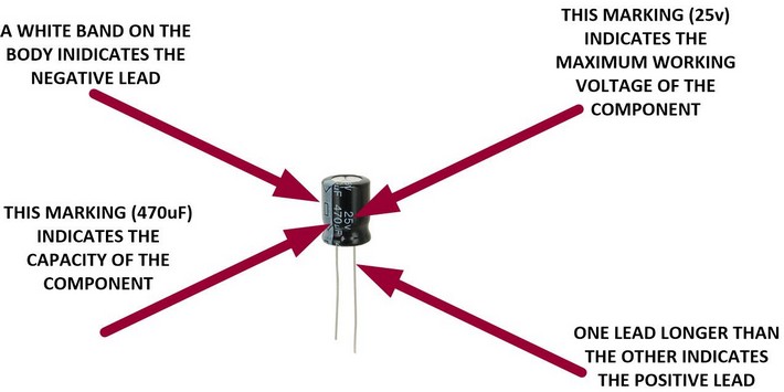
An electronic component has a body, or package, and some connections. There are markings on the package so you can identify the component and work out which way around to connect it. Some markings indicate the component's value, accuracy or maximum operating conditions. But some components, which have dozens of important qualities and quantities, simply have a code or "part-number" marking. You use the code to lookup and download a "datasheet" from the Internet. The datasheet will tell you everything you need to know about it. The following picture shows a capacitor and its markings.
The value of this component is 470uF, where uF is an abbreviation for micro-Farad. The value is made up of three things: A number (470), a multiplier (micro) and a unit (Farad). It is the same as any other value like 240kg, where kg is an abbreviation for kilogram and the value is made up of a number (240), a multiplier (kilo) and a unit (gram). The number and multiplier determines the amount of the unit provided by the component.
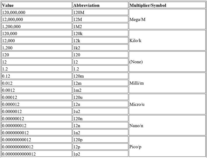
The multiplier can be any one of: Mega, kilo, milli, micro, nano, pico or no multiplier at all. The following table shows how multipliers and their symbols are used to abbreviate large and small values. Multipliers are very useful when having to print the value on the side of a small component: Instead of having to print 0.0000012F it can be abbreviated to 1u2F. Luckily, most circuit schematic diagrams use the abbreviations that are actually marked on the component to make it easier.

Resistors, on the other hand, are often too small to have letters and numbers printed on them. Instead they have brightly coloured bands to indicate their value, multiplier and accuracy. There are usually four colour bands. The first two bands indicates one of twenty-four different values: Either 10, 11, 12, 13, 15, 16, 18, 20, 22, 24, 27, 30, 33, 36, 39, 43, 47, 51, 56, 62, 68, 75, 82 or 91. The third band indicates the multiplier: Either 0.1, 1, 10, 100, 1000, 10000, 100000 or 1000000. The forth band indicates the accuracy or "tolerance" of the resistor. It is either silver (10% accuracy) or gold (5% accuracy).
The resistor colour code is as follows:
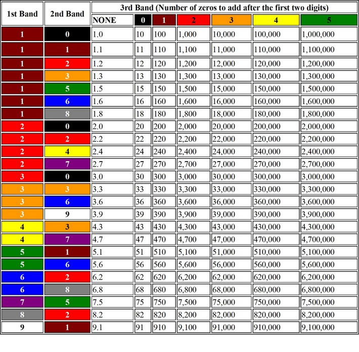
The following chart shows the colours representing all the possible resistor values. Use the first two colour bands to select the row then select the column using the 3 colour band. The third band actually represents the number of zeros added after the first two digits.
Example: A resistor with red, purple, yellow and gold bands has a value of 270,000 Ohms with 5% accuracy.
Component Types
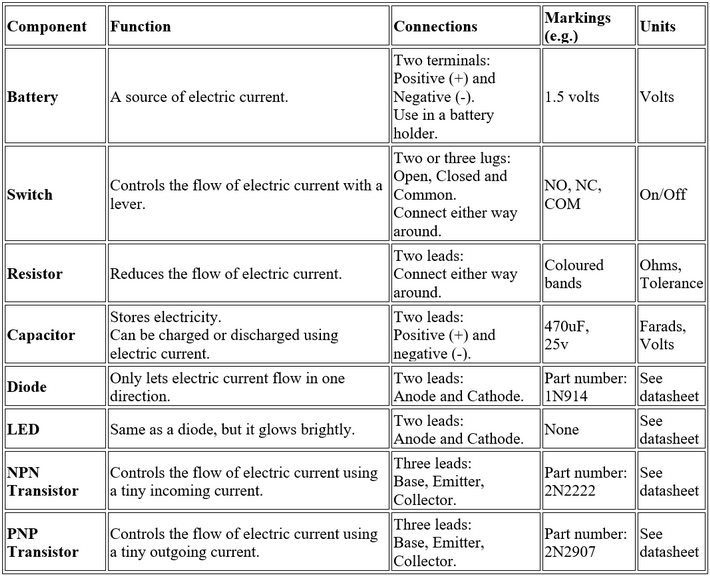
Here is a short list of some common electronic components, the tricks they can do with electric current and what the markings mean.
Component Symbols

Electronic components come in all shapes and sizes, so instead of trying to draw pictures of them all the time we use stick-figure symbols to represent each type. Let's have a look and some different types of components and their symbols:
Component Datasheet
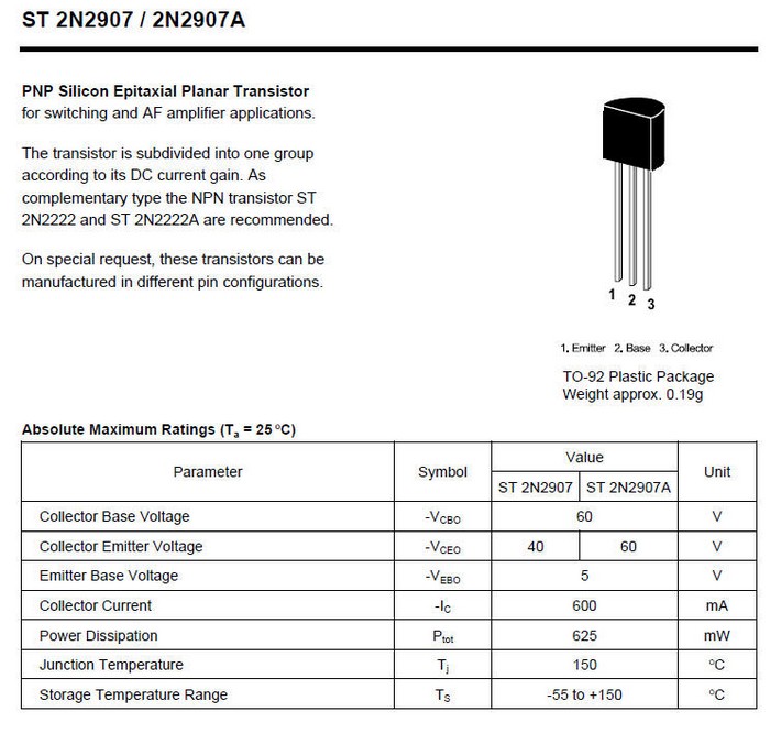
For information on electronic components with only part-number markings: Search the internet for a datasheet. Download it to see details of the different packages, leads, values, markings and even sample circuits to use them. Here is the datasheet for a 2N2907 PNP Transistor:
Component Tester

We can use a component tester to identify the type and value of most simple components with 2 or 3 leads. Put the component's leads into the tester's socket, close the lever and press the button. It will display the component type at the top of the screen; a circuit symbol showing which lead is which and the component values. Note: This PNP transistor does not have the same package as the one in the datasheet above. The pin functions are different: So it was very useful to check it!
Preparation
You will need:
- A large selection of small component types in a container.
- Data sheets for transistors.
- A resistor colour code chart.
- A capacitor multiplier chart.
- A magnifying glass.
- A component tester ($15 on eBay) and/or multimeter
- Pencils and paper.
Activity
Student identify the components by:
- Looking at them under a magnifying glass.
- Sketching the components on paper.
- Writing down the markings (coloured bands or labels) on the component.
- Using colour-code or multiplier charts or data sheets to decipher what the abbreviated markings mean.
- Using the component tester and/or multimeter to verify the type of component.
- Sketching the circuit symbol of the component next to its drawing.
When students can recognise the components by eye they can have a race to see who can sort a bucket of components the fastest.
Homework
Look around your school or home and play this game with your friends or family:
- Point to an object and say its resistor colour-code number. For example: Soil is 0, wood is 1, bricks are 2, a basket ball is 3, cheese is 4, grass is 5, the sky is 6, clouds are 8 or 9 etc.
- Ask them to guess what you are doing.
- Show them the resistor colour code chart.