
CTCSS Encoder
This is a simple Arduino project used to generate Continuous Tone Coded Squelch System (CTCSS) tones.
Continuous Tone Coded Squelch System
CTCSS enables a limited selective calling (SELCAL) function as follows: A low-frequency (sub-audible) tone from a CTCSS encoder is injected into the modulator of a transmitter and decoded in a compatible receiver fitted with a CTCSS decoder. The receiver is only unmuted when the correct CTCSS tone is detected. Standardized CTCSS tones are sinusoidal and in a frequency range of 67.0Hz - 254.1Hz. For more information, please see here.
CTCSS is now widely used in Amateur Radio VHF/UHF repeaters to stop them being keyed up by random man-made interference (QRM). This device can be retro-fitted to an older FM transceiver, which does not already have the CTCSS encoder capability, in order to permit repeater access.
Components
The CTCSS encoder comprises the following components:
- A 16MHz Pro Micro microcontroller - Arduino Leonardo compatible
- A 12-key numeric keypad
- A 2nd-order Low Pass Filter made from 1206 surface-mounted resistors and capacitors
- A 1N4148 reverse polarity protection diode
- Solderable enameled copper wire
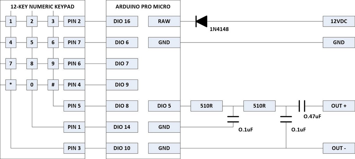
Schematic Diagram
The schematic diagram of the CTCSS encoder is shown below.
Theory of operation
Sequence:
- When the unit is powered up it generates the last valid CTCSS tone frequency entered
- The last valid frequency is recovered from the EEPROM
- The CTCSS tone frequency (in Hz) can also be entered on the keypad, using <*> for a decimal point and <#> for an enter key
- The 12-button keypad is scanned and the button-presses are debounced
- The user input is validated only after the <#> key is pressed
- Frequencies from 50.0Hz to 300Hz are deemed acceptable
- Only zero, one or two decimal places are used, but more can be entered
- The output frequency is only changed if the user input frequency is valid
- A valid user input frequency is used to populate a wave table with the amplitude values of one complete cycle of a sinewave
- A valid user input frequency is stored in EEPROM
- The length of the waveform stored in the wave table is variable and depends on the frequency chosen
- An ATmega32U4 Timer/Counter is used to generate a PWM waveform, constantly updated to approximate the required sinewave
- To produce a PWM waveform, with phase-correct transitions, the Timer/Counter works in a symmetrical up/down counting mode
- The PWM output is set and the 8-bit counter starts to count up from 0 to 255
- When the counter reaches the required sinewave amplitude value, as stored in its counter control register, the PWM output is reset
- The counter continues to count up to 255, but then reverses and starts to count down to 0
- When the counter reaches the required sinewave amplitude value, as stored in its counter control register, the PWM output is set
- Whatever the required sinewave amplitude, the PWM pulse is symmetrical about the counter mid-point and is therefore phase-correct
- This reduces the phase noise caused by transitions when updating the PWM value
- At the end of each up/down counter cycle the Timer/Counter is configured to generate an overflow interrupt
- The interrupt service routine for the Timer/Counter overflow interrupt is used to reload the counter control register with the next sinewave amplitude in the wave table
- The next value from the wave table is selected in a cyclic manner
- The 8-bit PWM waveform up/down cycle length is 2 * 256 = 512 samples at the processor clock frequency of 16MHz
- The 8-bit PWM waveform frequency is therefore 16000000 / 512 = 31,250Hz
- The wave table is sampled at the same rate
The diagram below shows the operation of the Timer/Counter in 8-bit, Phase Correct, Clear Output mode. The counter continuously counts up and down between 0 and 255. If the counter compare register is set to 224 (which is 7/8ths of 256), the PWM output will be high for 7/8ths of the PWM cycle.
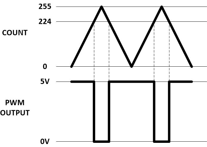
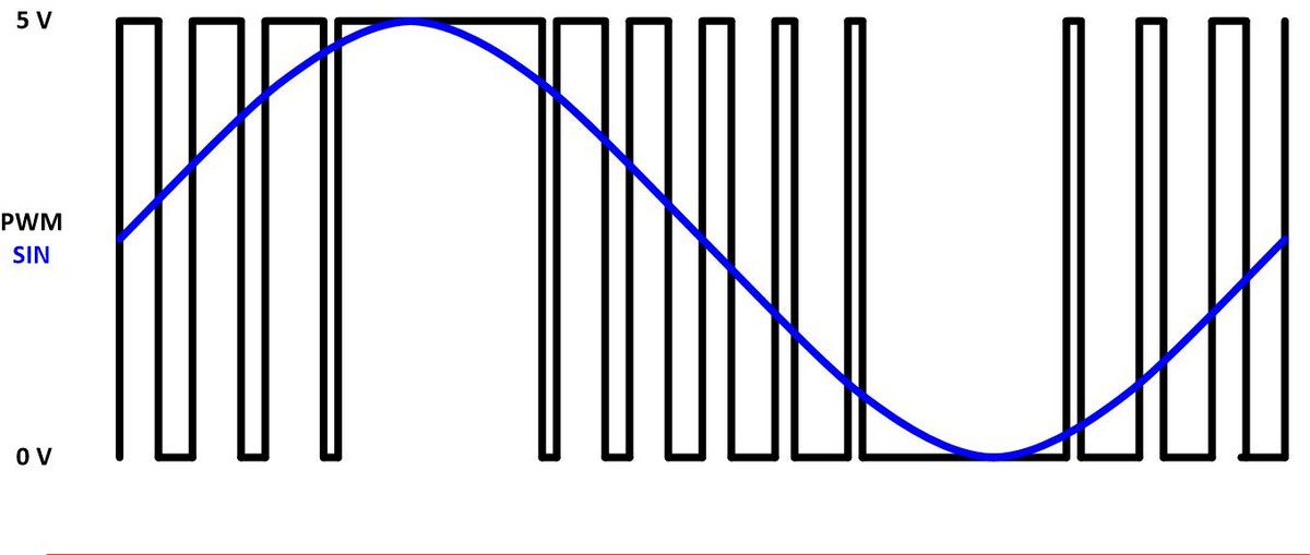
So, by constantly changing the counter compare register to match the amplitude of the required sinewave, a phase-correct PWM output is created that represents the sinewave. The actual analog sinewave signal can then be recovered from the PWM output using an external Low Pass Filter.
Counter/Timer3 configuration:
//See Atmel-7766H-USB-ATmega16U4_32U4-Datasheet_092014
//Set Timer/Counter Control Registers
//TCCR3A: COM3A1 COM3A0 COM3B1 COM3B0 COM3C1 COM3C0 WGM31 WGM30
//1 0 0 0 0 0 0 1
//Bit 7:6 – COMnA1:0: Compare Output Mode for Channel A
//Bit 5:4 – COMnB1:0: Compare Output Mode for Channel B
//Bit 3:2 – COMnC1:0: Compare Output Mode for Channel C
//Bit 1:0 – WGMn1:0: Waveform Generation Mode - PWM, Phase Correct, 8bit
//Timer/Counter Compare Output Modes
//0 0 Normal port operation, OCnA/OCnB/OCnC disconnected
//0 1 Toggle OC1A on Compare Match, OC1B and OC1C disconnected (normal port operation) only when WGM13:0 = 14 or 15:
//1 0 Clear OCnA/OCnB/OCnC on compare match, set OCnA/OCnB/OCnC at TOP
//1 1 Set OCnA/OCnB/OCnC on compare match, clear OCnA/OCnB/OCnC at TOP
//TCCR3B Bits: ICNC3 ICES3 - WGM33 WGM32 CS32 CS31 CS30
//0 0 0 0 0 0 0 1
//Bit 7 – ICNCn: Input Capture Noise Canceler - Off
//Bit 6 – ICESn: Input Capture Edge Select - Falling edge
//Bit 5 – Reserved Bit
//Bit 4:3 – WGMn3:2: Waveform Generation Mode - PWM, Phase Correct, 8bit
//Bit 2:0 – CSn2:0: Clock Select - Internal Clock No Prescaling
Low Pass Filter:
A Low Pass Filter (LPF) is required to smooth out the digital PWM signal to create an analog sinewave. The PWM signal has a frequency of 31250 Hz. The sinewave maximum frequency is only 300 Hz. A LPF with a -3dB cutoff of around 10 times that (3 kHz) is sufficient to remove the PWM signal and leave only the sinewave. Designing for a source impedance of around 1kΩ, a second-order LPF can be fabricated two 510Ω resistors and two 0.1uF capacitors. Using the formula: f = 1 / (2 Pi R C), the resulting cutoff frequency is around 3.1kHz. Following the LPF there is a 0.47uF DC blocking capacitor.
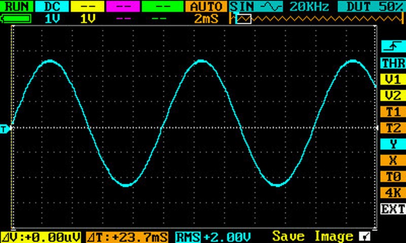
Analog Output Waveform 50Hz
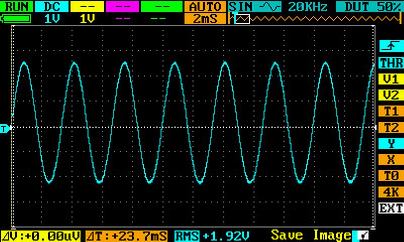
Analog Output Waveforms 300Hz
Specifications
- Supply voltage: 6 - 15 VDC (Be careful: We had a report of one on-board regulator failing at 11.3V! - Maybe a clone?)
- Supply current: 38 mA
- Frequency range: 50.0 Hz - 300.0 Hz
- Frequency accuracy: About +/- 0.5%
- Output Impedance: 1k Ohms
- Output level: 2 Vrms into no load
- Panel cutout size: 55 mm x 44 mm
Software
The Arduino sketch can be downloaded here.
Unzip the contents of the zip file to the Arduino IDE sketch Folder.
Project Status (Updated: 3 February 2023)
Total number of reported builders: 81
Please update your status by e-mailing us. You can send us pictures and reports of your progress.
Construction
The CTCSS encoder is constructed by attaching the Arduino Pro Micro to the rear of the keypad using clear, wet-area, silicone, sealant. Only a thin, central, vertical stripe of sealant is required on the back of the Arduino Pro Micro. However, the Arduino Pro Micro should be positioned such that its micro USB connector is accessible at the top of the keypad. This connector is used for programming the device. Note: Fill the PCB holes with solder prior to assembly, so as to exclude any excess sealant from them.
The keypad and other components are wired, as shown, using solderable enamelled copper wire. Tin the ends to burn off the enamel before soldering. The SMT components could also be glued to the back of the keypad, but this is unnecessary. Small, tinned, loops are provided for connection of the external cables.
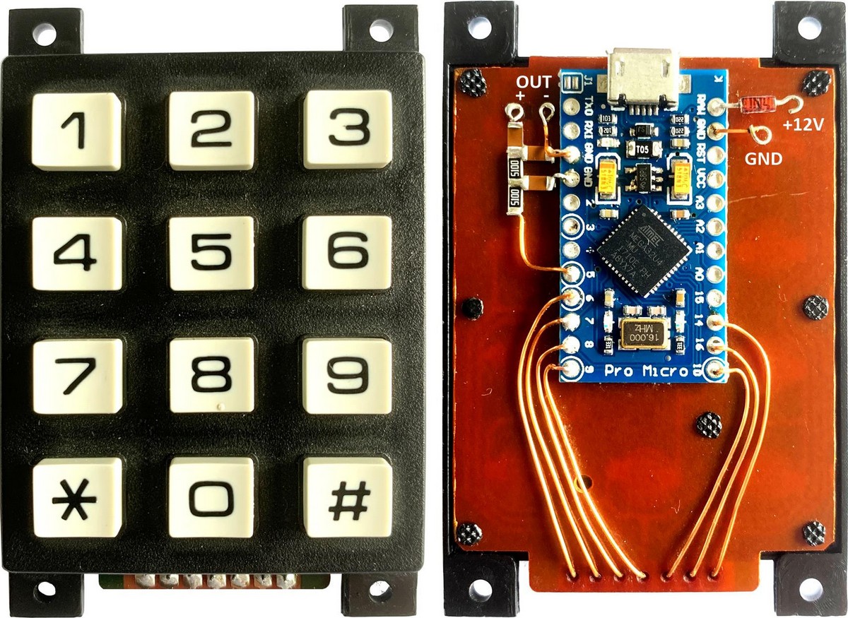
Front CTCSS Encoder Rear
Installation
The final installation is up to the user. The unit can be mounted in a separate enclosure. In some cases the unit can be mounted behind a panel of the transceiver. The 12 V DC input of the unit is wired to the 13.8 V DC, switched, power supply bus of the transceiver, using thin twin-core cable. The audio output of the unit is wired to the transceiver microphone connector or modulator circuit using thin screened cable. The user will need to adjust the audio level into the transceiver, using an attenuator pad or potentiometer. The level should be adjusted to the minimum required for reliable operation.
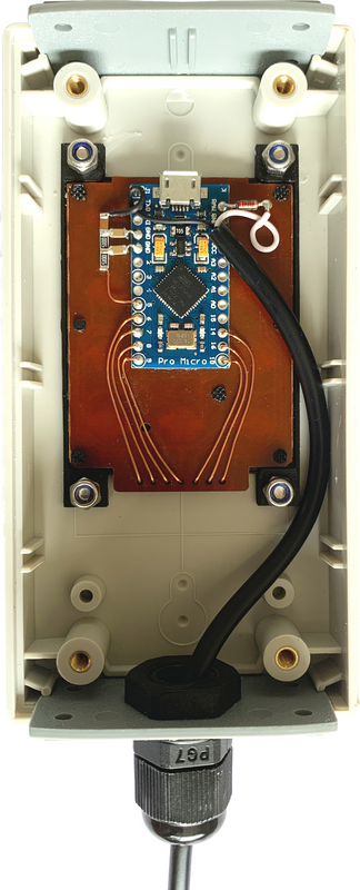
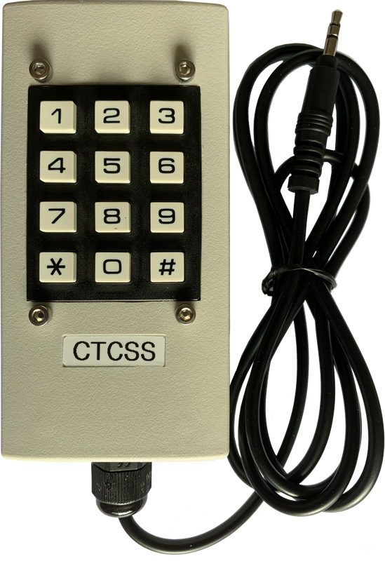
CTCSS Encoder Mounted in Enclosure with Cable