
SARCTRAC Mk2
Satellite Antenna Rotator Controller and TRACker - Discontinued
SARCTRAC Mk2 is no longer available as a fully assembled, tested and calibrated product. We do not provide separate SARCTRAC software.
SARCTRAC Mk2 is a portable, integrated, satellite tracking system, which is now available as a fully assembled, tested and calibrated product. Simply mount it on your tripod; attach it to your hand-held satellite antenna using a counterbalanced lift-arm; connect it to your radio transceiver and battery; strap on the SARCTRAC 3D sensor to your antenna boom; then use your WiFi-enabled mobile device to control SARCTRAC and select the satellites you want to track. SARCTRAC will predict future satellite passes, track each satellite in turn and even tune you radio to the correct frequency for each overhead pass. With a SARCTRAC system and your own equipment you can listen to orbiting space beacons, make two-way satellite contacts and use free, third-party software to download earth images and decode satellite telemetry. It's both fun and educational! Note: SARCTRAC comes with its own test stand and a test lift-arm for demonstration purposes.
New for 2020: The Amateur Radio International Space Station (ARISS) team and NASA have installed a permanent radio repeater on board the ISS. So now you can use SARCTRAC to listen and talk to other Amateur Radio enthusiasts via the ISS!
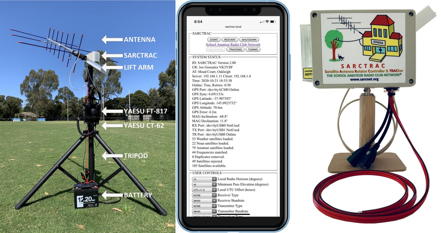 SARCTRAC Mk2 Portable Setup, SELECTION Page and Test Setup
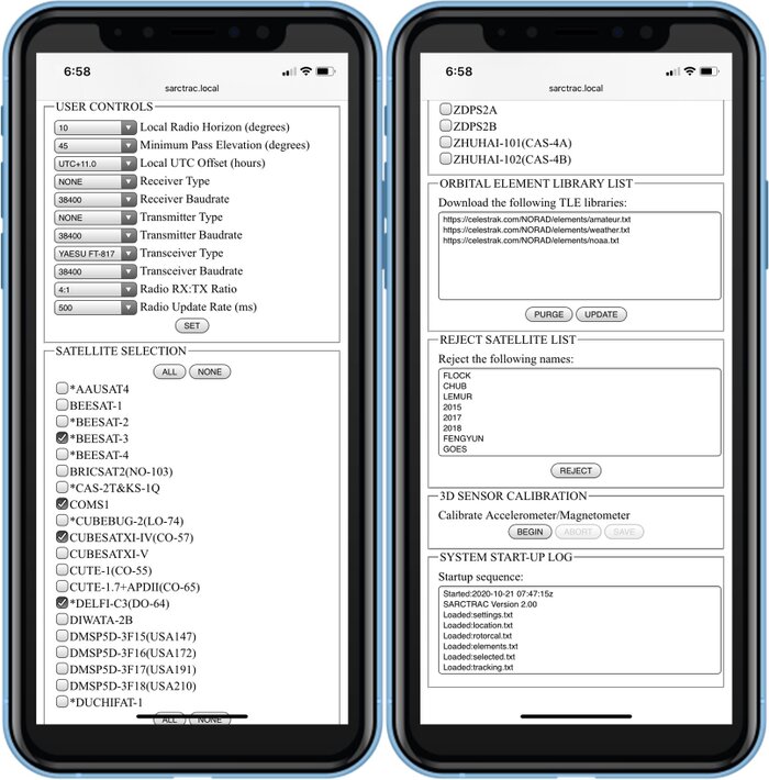
SARCTRAC Mk2 SELECTION Page
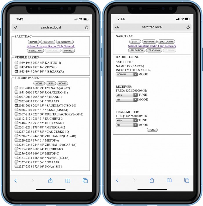
SARCTRAC Mk2 TRACKING and TUNING Page
Introduction
SARCTRAC was developed so that students at our School Amateur Radio Clubs can have fun and learn about Low Earth Orbiting satellites during our lunchtime sessions.
SARCTRAC takes minutes to set up, in the playground, on a mountain summit, down at our local footy oval or even in the backyard. It starts tracking visible satellites from the selected satellite list right away. To listen and talk to satellites we like to use our Yaesu FT-817 radio, but for some satellites you can just use a hand-held, VHF/UHF FM radio, or even a pair, so you can hear your own signal coming from the satellite. Our School Amateur Radio Club students think SARCTRAC is really fascinating to watch - and so do we. They try to imagine where the satellite is, by looking along the antenna boom and ask: "It's up there?"
The inspiration for SARCTRAC was to help little kids have fun in space: Well, at least to play with things in low earth orbit! You might be surprised just how many tiny cube-sats and regular polar-orbiting satellites there are. The first challenge is to know when are where the satellites will be. Then to point a hand-held antenna up at them for about 10 minutes while they pass overhead. You also have to constantly adjust your radio transmitter and receiver frequencies to compensate for something called Doppler shift. It turned out that our young radio enthusiasts found all that quite challenging, which detracted from the fun of getting to know our new friends in space. It was hard for us, too, just getting everything to work at different schools: So we set about to design a fully automated system.
To make friends with a satellite you first have to know when and where it will be; point a small, directional antenna at it and use an Amateur Radio transceiver to listen or talk through it. It is a bit like fishing in the sky and just as challenging. It is really exciting when the kids hear their first satellite and then realise where it is. They always ask. “Can we talk to it?” We say. “Of course, you can.” But the reality is that satellites move so fast that their position and radio frequency is constantly changing. Tracking a satellite by hand, while trying to tune an Amateur Radio transceiver for a typical 10-minute overhead pass, is a real chore for kids. Setting up an automatic tracking system, with a commercial antenna rotator and all the computers, cables and programs needed, is both tricky and expensive. So, we designed SARCTRAC to be quick and easy for the kids to set up, and now, it does all the work for them. SARCTRAC helps kids spend more time listening to signals from space, receiving data or pictures and even communicating with others via satellites. School kids in space? We say "No problems"!
History
We first introduced our free, Arduino-based, "Mini Satellite-Antenna Rotator" in 2015. It was a great success, with over 900 radio enthusiasts from around the world building one. Unfortunately, sourcing the correct components, compiling and uploading the software and calibrating the sensor was too much for many who attempted building it. Let alone the pitfalls of setting up and using third-party, satellite-tracking software. And, as much as we love helping our readers out, we realised that we were spending more time supporting them than developing new projects for the kids.
We partly solved that problem by designing an integrated satellite tracking system that just works: SARCTRAC Mk1 took us over 15 months to develop and was the second generation of our 3D-Sensor based antenna rotator. It was half the size of the original unit with many new features. SARCTRAC Mk1 was offered as a DIY kit with all the parts and software required. Unfortunately, it only supported one type of radio: The Yaesu FT-817 and was only suitable for the experienced builder. So, we were still confronted with a large support effort.
In 2020, due to the COVID-19 pandemic, we experienced parts shortages, freight delays and months of home isolation. So we spent another 5 months re-designing and developing SARCTRAC Mk2, with many more new features. We offered the first 40 units as a fully assembled, tested and calibrated product. This approach provided us with a wealth of experience in the production process. In the end we decided this was the only way to ensure quality components, production processes, reduced support effort and, ultimately, reader satisfaction. We expect to continue our small-scale production effort of fully assembled, tested and calibrated SARCTRAC Mk2 products next year, even though our primary goal is introducing STEM to school kids using Amateur Radio.
Features
- Setup
- Tripod-mounted for portable operation and quick set-up - Easily splits into two separate pieces: Tripod/rotator and antenna/lift-arm.
- DC powered for battery or solar operation - Typically uses the same power source as the radio.
- Integrated rotator and controller in one unit - Smaller with less cables. No third-party tracking software to wrestle with.
- Networking
- WiFi enabled - Works with home WiFi network or WiFi-enabled mobile device with personal hotspot and broadband Internet connection.
- Internet enabled - Automatically downloads date, time and satellite orbital elements from the Internet.
- WiFi enabled mobile device used for control and display - No cables to separate PC or laptop.
- Built-in web server accessible by any web browser on the WiFi network - No tracking applications to install and configure.
- Start-up
- Displays satellite SELECTION, satellite TRACKING and radio TUNING web pages - Logically organised pages.
- Start-up alert tones - Warn of disconnected USB CAT Cable, GPS or 3D Sensor.
- Access to START/STOP, RESTART and SHUTDOWN buttons on each web page - Important for rotator safety and tracker control.
- Starts with motors stopped - Operator action is required to start motors after power up for safety.
- Displays Local Time with Time Zone selection - Easier for scheduling.
- Date and time information provided by built-in GPS receiver or Internet time source - No clock setting required.
- Latitude and Longitude information provided by built-in GPS receiver - No station location entry required.
- Uses last saved location until GPS is available - Quicker startup.
- Stops polling GPS when location error is minimised - Reduces processor load.
- Displays reverse geocode address lookup - Confirms that the correct latitude and longitude is used.
- Antenna pointing information provided by boom-mounted 3D Sensor (magnetometer/accelerometer) - No compass calibration or leveling required.
- Magnetic inclination and declination information provided by built-in World Magnetic Model - No online searching for local magnetic offsets.
- Satellite orbital element information updated from Internet each day - No manual download required.
- Satellite position determined from the latest SGP4 orbital predication models - More accurate tracking.
- Uses last saved satellite selection - Quicker startup.
- Satellite Selection
- Access to thousands of satellite orbital elements over the Internet - Distributed by Dr. T.S. Kelso at www.celestrak.com since 1985.
- Permits user-entry of selected orbital element library URLs - Select which satellite libraries are of interest.
- Each orbital element library contains hundreds of satellites in different categories, like weather, cube-sats, amateur and NOAA - Select only the categories you want.
- Permits loading of user-defined orbital element library files - Load pre-launch or unlisted orbital elements.
- Permits user entry of satellite names to be rejected - Omit whole series of unwanted satellites from the satellite selection list.
- Displays satellite statistics: Number of each type loaded, duplicates removed, number rejected and the total available - Helps manage your satellite database.
- Satellite Tracking
- Tracks only selected satellites - Schedules tracking of each satellite in turn.
- Satellites displayed in order of their Acquisition Of Signal (AOS) time - Provides a next pass schedule.
- Displays next-pass, AOS time, azimuth and max elevation for each selected satellite - Easy to decide which satellite passes to track.
- Displays currently tracked satellite azimuth, current elevation and LOS time - Easy to compare current satellite LOS time with next satellite AOS time.
- Automatically points the antenna at a visible satellite - No manual antenna steering required.
- Built-in alert tone indicates immanent antenna movement - Safer operation. Alerts at the start and end of the current pass.
- Permits selection of any one of multiple visible satellites - Compare and select the best of the currently visible passes.
- Automatically re-positions antenna ready for the next pass - No waiting at the start of each pass.
- Motor stall warning with anti-stall shaker - Prevents motors stalling uner certain conditions.
- Intelligent anti-windup algorithm - Unwinds the cables in between passes.
- Tracks multiple selected satellites in turn - No resetting selections between passes.
- Radio Control
- Radio CAT control enabled - Automatically controls the radio frequencies and modes.
- Automatically controls the radio frequencies correcting for satellite Doppler shift - Accurate frequency control.
- Satellite beacon/transponder frequency and mode information provided by built-in satellite database - No online searching for satellite data.
- Permits selection of known satellite beacons or transponders - Useful to check the beacon frequency if the transponder is not heard.
- Permits manual adjustment of transmit and receive frequencies and modes - Useful to avoid interference and use the transponder bandwidth more efficiently.
- Sensor Calibration
- 3D Sensor is calibrated at the factory. Recalibration is possible if magnetic conditions change.
- Provides manual Start, Abort and Save calibration controls with tone feedback - Easier and more accurate calibration.
- Miscellaneous
- Reduced Radio Frequency Interference using analog regulators and RF chokes - Easier to hear selected satellites.
- DC reverse polarity protection - Setup at night with no more smoke and tears.
- Stall resistant motors and gearboxes with all metal gears - Safer operation with longer lasting gearboxes.
- Field upgradable for new versions of Hamlib
New Features
SARCTRAC Mk2 provides the following new features over the original SARCTRAC Mk1:
- New Raspberry Pi 3B+ 1.4GHz Quad Core processor with 2.4/5GHz WiFi
- New Raspbian Buster Operating System
- New Enclosure with low noise analog regulator and external heatsink
- New Radio Types supported for Doppler frequency correction
- New Transmitter and Receiver pairs supported as well as Transceivers
- New Local Radio Horizon displays realistic AOS and LOS times in built-up areas
- New Minimum Pass Elevation displays only future passes above a minimum elevation
- New Pass Predictor displays multiple passes of each satellite
- New Realtime display updates of visible and future passes every 5 seconds
- New Single-Touch satellite and pass selection controls
- New More/Less Passes and Home buttons
- New Anti-Windup algorithm - Unwinds cables to the home position
- New Anti-Stall algorithm - Detects, alerts and rectifies motor stall conditions
- New Fast Multi-Threaded compiled code with Quad-Core parallel processing
- New Production-Quality Web Server
- New Object-Oriented Design: Written in Python 3 - Cross compiled to C++
- Powered by CelesTrak: Two-Line Elements since 1985 by Dr. T.S. Kelso
- Powered by Skyfield: Elegant Astronomy for Python by Brandon Rhodes
- Powered by World Magnetic Model: 24/3/2020 by NCEI and geomag by C.Weiss
- Powered by Nominatim: Reverse geocoding for Open Street Maps
- Powered by Hamlib: Ham Radio Control Library
- Powered by Flask: Web Development One Drop At A Time
- Powered by Waitress: Production Quality WSGI Server
Links
SARCTRAC Mk2 - Discontinued
SARCTRAC Mk2 is no longer available as a fully assembled, tested and calibrated product.SARCTRAC Mk2 Production - See how SARCTRAC is made SARCTRAC Mk2 Forum - Share your SARCTRAC Mk2 experience SARCTRAC Mk2 Video - See SARCTRAC in operation SARCTRAC Mk2 Quick Start Guide - Get going with SARCTRAC (4 Pages, 520kB, PDF) SARCTRAC Mk2 Manual - Setup and Operate SARCTRAC (54 Pages, 2.0MB, PDF) SARCTRAC Mk2 3D Sensor Factory Calibration - See SARCTRAC being calibrated
Specifications
- Enclosure Size: 145x105x65mm (5.7x4.1x2.2inch)
- Sensor cable length: 1m
- Power cable length: 1m
- USB 2.0 Ports: 2
- WiFi: 2.4/5GHz
- Ingress protection: IP68 sensor. IP65 enclosure.
- Operating voltage: 12-15VDC (min - max)
- Operating current: 1A (typical)
- Overcurrent protection
- Overtemperature protection
- Reverse polarity protection
- Regulatory Compliance: See below
- Typical start-up time: 30 seconds
- Typical flash-upgrade time: 10 minutes
- Antenna rotation speed: 0.6 RPM (3.6 degrees per second) azimuth and elevation (max)
- Local Radio Horizon: 0-20 degrees in 1 degree increments.
- Minimum Pass Elevation 0-45 degrees in 5 degree increments
- Radio RX:TX Ratio: None, 1:1 to 9:1
- Radio Update Rates: 100, 200, 500, 1000, 2000, 5000 milliseconds
- Radio modes supported: AM, FM, CW, USB and LSB
- Radio baudrates supported: 1200, 2400, 4800, 9600, 19200, 38400, 57600, 115200
- Supported receivers/transmitters: Only receivers/transmitters supported by HAMLIB's F and M commands. See Radio Control.
- Supported transceivers: Only transceivers supported by HAMLIB's F, M, I, X and S commands. See Radio Control.
- Supported USB CAT cables: Only USB to serial converters with compatible voltages and connectors that use devices supported by Linux including genuine chipsets such as FTDI, CH-340, but not PL2303. See Radio Control.
- The following radios have been verified to work, with the following anomalies identified in the Radio Control section:
- Yaesu FT-817: RX clicks, TX lockout, VFO switching and RIT/XIT Override.
- The following USB CAT cables have been verified:
- Yaesu CT-62.
- Yaesu CT-62 copies with genuine FTDI chips.
- CH-340 USB-TTL converters.
Radio Control
Important: We do not claim any particular radio or CAT cable is supported until we have either verified it ourselves or have received credible reports of its interoperability. Until then, radio control comptability is considered either an experimental or non-existent feature. Notwithstanding this, our research shows that an indication of possible radio interoperability may be obtained from the HAMLIB version 3.3 rigctrl program, itself, which reports support for the specific radios shown in the following list.
Where:
R = A Receiver, with a serial control port, which supports the HAMLIB F and M commands.T = A Transmitter, with a serial control port, which supports the HAMLIB F and M commands.X = A Transceiver, with a serial control port, which supports the HAMLIB F and M commands and in addition supports split mode VFO operation using the HAMLIB I, X and S commands.
- A transceiver should be capable of operating as either a receiver or transceiver.
- The first USB device plugged in is assigned to USB0.
- The second USB device plugged in is assigned to USB1.
- if two USB devices are plugged in at power up they are consistently assigned as USB0 and USB1 respectively. In this case the USB0 port is indicated by a silver dot on the connector.
Unavoidable anomalies with radio control:
- RX Click: Some receivers produce an audible "click" or audio blanking whenever the receiver VFO is updated.
- TX Lockout: Some transmitters and transceivers do not permit their frequency to be changed while transmitting.
- VFO Switching: Some transceivers must switch to the transmitter VFO to update it, causing momentary reception of the uplink frequency.
- RIT/XIT Override: Some receiver’s RIT and transmitter’s XIT controls are unusable because they are overridden by the RX/TX VFO CAT control. Hence the provision of TX and RX offset tuning on the SARCTRAC Tuning Page.
RadioType RadioModel, RadioCapability
- ADAT WWW.ADAT.CH, T
- AOR AR2700, R
- AOR AR3000A, R
- AOR AR3030, R
- AOR AR5000, R
- AOR AR5000A, R
- AOR AR7030, R
- AOR AR7030, R
- AOR AR8000, R
- AOR AR8200, R
- AOR AR8600, R
- AOR SR2200, R
- DRAKE R-8A, R
- DRAKE R-8B, R
- ELECRAFT K2, X
- ICOM IC, T
- ICOM IC-1275, T
- ICOM IC-271, T
- ICOM IC-2730, X
- ICOM IC-275, T
- ICOM IC-471, T
- ICOM IC-475, T
- ICOM IC-7000, X
- ICOM IC-703, X
- ICOM IC-706, X
- ICOM IC-706MKII, X
- ICOM IC-706MKIIG, X
- ICOM IC-707, X
- ICOM IC-7100, X
- ICOM IC-718, X
- ICOM IC-7200, X
- ICOM IC-725, X
- ICOM IC-726, X
- ICOM IC-728, X
- ICOM IC-7300, X
- ICOM IC-735, T
- ICOM IC-736, X
- ICOM IC-737, X
- ICOM IC-738, X
- ICOM IC-7410, X
RadioType RadioModel, RadioCapability
- ICOM IC-746, X
- ICOM IC-746PRO, X
- ICOM IC-751, T
- ICOM IC-756, X
- ICOM IC-756PRO, X
- ICOM IC-756PROII, X
- ICOM IC-756PROIII, X
- ICOM IC-7600, X
- ICOM IC-761, T
- ICOM IC-7610, X
- ICOM IC-765, X
- ICOM IC-7700, X
- ICOM IC-775, T
- ICOM IC-78, T
- ICOM IC-7800, X
- ICOM IC-781, X
- ICOM IC-785X, X
- ICOM IC-820H, T
- ICOM IC-821H, T
- ICOM IC-910, X
- ICOM IC-9100, X
- ICOM IC-970, T
- ICOM IC-PCR100, R
- ICOM IC-PCR1000, R
- ICOM IC-PCR1500, R
- ICOM IC-PCR2500, R
- ICOM IC-R7000, R
- ICOM IC-R71, R
- ICOM IC-R7100, R
- ICOM IC-R72, R
- ICOM IC-R75, R
- ICOM IC-R9000, R
- ICOM IC-R9500, R
- ICOM ICR-8500, R
- ICOM ID-5100, X
- JRC NRD-525, R
- JRC NRD-535D, R
- JRC NRD-545, R
- KENWOOD R-5000, R
- KENWOOD TH-D72A, T
RadioType RadioModel, RadioCapability
- KENWOOD TH-D7A, T
- KENWOOD TH-F6A, T
- KENWOOD TH-F7E, T
- KENWOOD TM-D700, X
- KENWOOD TM-D710(G), T
- KENWOOD TS-140S, T
- KENWOOD TS-2000, X
- KENWOOD TS-440, X
- KENWOOD TS-450S, X
- KENWOOD TS-480, X
- KENWOOD TS-50S, X
- KENWOOD TS-570D, X
- KENWOOD TS-570S, X
- KENWOOD TS-590S, X
- KENWOOD TS-590SG, X
- KENWOOD TS-680S, T
- KENWOOD TS-690S, X
- KENWOOD TS-711, T
- KENWOOD TS-790, X
- KENWOOD TS-811, T
- KENWOOD TS-850, X
- KENWOOD TS-870S, X
- KENWOOD TS-930, T
- KENWOOD TS-940S, X
- KENWOOD TS-950SDX, T
- KENWOOD TS-990S, X
- LOWE HF-235, R
- MICROTELECOM PERSEUS, R
- OPTOELECTRONICS OPTOSCAN456, R
- OPTOELECTRONICS OPTOSCAN535, R
- RACAL RA3702, R
- RACAL RA6790/GM, R
- ROHDE&SCHWARZ EB200, R
- ROHDE&SCHWARZ ESMC, R
- ROHDE&SCHWARZ XK2100, T
- TAPR DSP-10, T
- TEN-TEC DELTA, T
- TEN-TEC OMNI, T
- TEN-TEC RX-320, R
- TEN-TEC RX-331, R
RadioType RadioModel, RadioCapability
- TEN-TEC RX-340, R
- TEN-TEC RX-350, R
- TEN-TEC TT-516, X
- TEN-TEC TT-538, X
- TEN-TEC TT-565, X
- TEN-TEC TT-585, X
- TEN-TEC TT-588, X
- TEN-TEC TT-599, X
- WATKINS-JOHNSON WJ-8888, R
- XEIGU X108G, X
- YAESU FRG-100, R
- YAESU FRG-8800, R
- YAESU FRG-9600, R
- YAESU FT-100, X
- YAESU FT-1000D, X
- YAESU FT-1000MP, T
- YAESU FT-1200, X
- YAESU FT-2000, X
- YAESU FT-450, X
- YAESU FT-736R, X
- YAESU FT-747GX, X
- YAESU FT-757GXII, T
- YAESU FT-767GX, X
- YAESU FT-817, X
- YAESU FT-840, X
- YAESU FT-847, X
- YAESU FT-857, X
- YAESU FT-890, X
- YAESU FT-897, X
- YAESU FT-900, X
- YAESU FT-920, X
- YAESU FT-950, X
- YAESU FT-980, T
- YAESU FT-990, X
- YAESU FT-DX5000, X
- YAESU FTDX-9000, X
- YAESU MARK-V, T
- YAESU MARK-V, T
- YAESU VR-5000, R
Design Notes
The following design notes are included here for those interested in some of the more difficult design trade-offs.
Radio Frequency Interference
Anyone having used a Raspberry Pi for Amateur Radio applications will be well aware of the RF noise produced by these little 1.4GHz, quad-core, powerhouses. Putting one right next to the receiving antenna would, therefore, not seem a sensible thing to do. However, in this application, it is unavoidable, since the 3D sensor must be mounted on the antenna boom and the I2C bus, which connects it to the RPi, does not work much over 1 metre of unshielded cable (less if shielded). To be able to receive week signals from satellites, we needed to keep the RFI to a minimum. Using a short antenna probe on the end of a flying, coaxial, lead connected to a Yaesu FT-817, we found that the main sources of RFI in the SARCTRAC application were:
- 5V Power Supply
- Raspberry Pi 3B+
- I2C bus
- DIO lines
- DC Motor commutators
The RFI from the 5V power supply, which powers the RPi, was absolutely incredible! It produced s9+ noise levels all over the VHF and UHF bands, within 1 metre of the operating unit. A dozen different AC plug-packs, AC inline power supplies and 12VDC - 5VDC switch-mode converter modules were tried with little success. Most of the RFI appeared to be coming from the wires connected to the input side of the DC/DC converter of the power supply. Various types of RF chokes, bypass capacitors, pi-filters and shielding were tried, producing only minor improvements. The only effective solution we found was to use a linear, regulated power supply. In the end, the reduction of RFI was a clear priority over the additional power dissipation, extra heat, size and the huge production effort required for SARCTRAC to have its own linear power supply. See below for details.
The RFI from the RPi itself, running off a linear regulated 5V DC power supply, was considerably less. It also produced s9 noise levels all over the VHF and UHF bands, but only with the probe coming into close proximity with the power supply, I2C and DIO wires themselves. At 1-metre, the noise reduced to s0, but was still audible. Unfortunately, if you need its optimum performance and features, the RFI coming from the RPi is effectively unavoidable. Most of the RFI comes from the onboard 3.3V/1.8V DC/DC converter. The RPi draws about 1A at 5V when operating. There are a plethora of ways to reduce RPi power consumption to a minimum, by using software configuration options. That could, potentially, cause a reduction in RFI. In short, we tried them all. The reduction in power consumption and RFI was negligible. Upon further investigation, and as expected, the source of the RPi RFI is on the input side of the onboard DC/DC converter. We found that putting the 5V power supply wires through an RF choke helped reduce the RFI coming from those wires to about s6. So we did.
The I2C bus was also a source of RFI. We found that we could reduce it considerably by reducing the I2C clock rate to 10kbps without affecting the performance of the application. So we did that too.
The DIO lines to the Motor Driver were also a source of RFI. We ran them through the same RF choke as used on the 5V power wires and that helped reduce the RFI next to those wires to about s6.
The DC motor commutators arc a little while operating, producing a clicking sound similar to motor-car ignition noise. In the past we had tried 0.1uF bypass capacitors on the motor terminals to the motor chassis. However, this solution didn't seem to have much effect with SARCTRAC and the interference was negligible, so we left it off.
The result of the above efforts was the reduction of RF wide-band noise from s9 levels across the VHF and UHF bands (i.e. unusable) to an acceptable s0 (on the FT-817 meter) with only some slightly audible processor noise on VHF. Some birdies from the processor may still be present, but these were not disruptive as they pass quickly with Doppler frequency control engaged. The measurement conditions were as follows: Yaesu FT-817 (146/437MHz, USB, RF Gain set to max) connected via the front antenna jack to an Arrow II 146/437-10 Antenna with inbuilt 2m/70cm duplexer.
Linear Regulated Power Supply
Having to use a linear regulated power supply for the 5VDC RPi 3B+ with an input of 12-15VDC was unavoidable. It had its own complications: The RPi dissipates 5W. The linear power supply dissipates 7-10W. We got away with using a small internal heatsink for the RPi Zero in SARCTRAC Mk1. Clearly that was not going to work here. So we designed and manufactured our own aluminium heatsink to fit the enclosure. It measures 80x40x25mm, has six fins and has a surface area of 22,400mm^2. The temperature of the heatsink rises to 50 degrees Celsius at an ambient termperature of 20 degrees Celsius. Hence the "CAUTION HOT" sticker. It isn't efficient, but its role in reducing the RFI to acceptable levels cannot be understated.
Safety
Please read the following very carefully. We accept no responsibility or liability for the following:
- This is partly a DIY construction project for the experience builder. We are not responsible for your time, costs, tools, availability or substitution of parts.
- Beware of moving parts - Unit may move at any time without warning. Do not stand or permit anyone to stand in the vicinity of the operating unit.
- Beware of eye hazard - Moving satellite antennas are prickly. Eye protection is recommended.
- Beware of pinch hazard - Keep fingers away from moving parts.
- Beware of electromagnetic radiation hazard - Do not use with high power transmitters. Recommend: 10 Watts maximum.
- Beware of electrocution hazard - Do not use near power lines.
- Beware of lightning hazard - Do not use in thunderstorms, rainy or windy conditions.
- Beware of burn hazard - The heatsink temperature may exceed 50 degrees. Do not touch it. Read the warning.
- Not suitable for unattended operation - Errant movement may cause injury, cable damage or antenna damage.
- Not suitable for fixed or permanent outdoor operation.
- Automatically connects to the Internet: Adult permission and charges may apply.
- Constant adult supervision of the operation is required to prevent injury, especially around children.
- Constant adult supervision of the operation is required to prevent damage to the unit, anything attached to the unit or anything in the vicinity of the unit.
- Constant adult supervision of the operation of radio transmitters is required at all times. You must check your licence conditions and operating frequency.
- Antenna, tripod, lift-arm, mountings, cables or anything in the vicinity of the unit may be damaged under normal operation or due to software malfunction.
- The motors are light-duty: Do not force them or drop or bump the tripod to avoid striping the metal gears.
- Installation of a safety DC cut-off switch is recommended.
Safety Testing
We have conducted the following safety testing of the completed product:
- Motor stall: The motors do not overheat or draw excessive current under continuous, full-power, stalled conditions.
- Antenna impact: The Arrow™ Antenna elements were not damaged under full-power impact with stationary objects or under continuous, restraint conditions.
- Human impact: The human operator was not damaged under full-power impact with the antenna. Note: Eye damage could occur even when the antenna is motionless. Touching the operating heatsink for 10 seconds did not produce a burn.
Regulatory Compliance
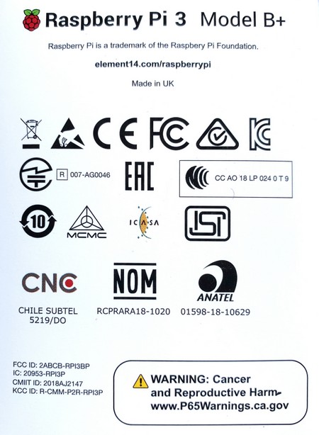
- SARCTRAC is essentially an embedded Raspberry Pi 3B+ (RPi) computer. The declarations of conformity, including local and regional approval certificates for the RPi can be found here. This covers: USA, Argentina, Australia, Bolivia, Brazil, Canada, Chile, China, Colombia, Costa Rica, Dominican Republic, Ethiopia, Ecuador, Guatemala, Hong Kong, India, Israel, Japan, Kenya, Malaysia, Mexico, New Zealand, Nicaragua, Panama, Peru, Philippines, Russia, Rwanda, Serbia, Singapore, South Africa, South Korea, Taiwan, Tanzania, Thailand, Turkey, Uganda, Uruguay and Venezuela. The RPi regulatory compliance marks are shown in the figure.
- SARCTRAC has a technical folder, which indicates it comprises an RPi together with additional electronic components and assemblies such as small motors, drivers, sensors and USB devices.
- SARCTRAC operates on 12-15VDC @ 1A and complies with Separated Extra Low Voltage (SELV) device requirements.
- SARCTRAC has been assembled with lead-free components and solder and complies with Restriction of Hazardous Substances (RoHS) requirements.
- SARCTRAC uses an RPi, which has been tested to meet international RFI/EMC requirements. SARCTRAC uses additional sensors, drivers and motors, which due to their nature and operating conditions would not affect this base RFI/EMC qualification. In fact, the reduction of RFI to nearby receivers and EMC with nearby transmitters, to levels well below international standards, was a key design requirement of this product.
- SARCTRAC introduces additional safety risks, which have been fully identified above. Some operational safety testing has been carried out to qualify the safety risks as minor. The additional safety risks have been reduced, by design, to as low as is reasonably practicable.
Limitations
- Only suitable for rotating a single, small, directional antenna (e.g. A handheld, dual-band, Yagi antenna such as an Arrow™ II antenna) using a counterbalanced lift-arm.
- May be suitable for controlling some radios, which are themselves controllable using HAMLIB commands: F, M, X, I and S via a USB CAT Cable. See radio control caveats and the list of possibly suitable radios.
- Will not work indoors: GPS and satellite antennas require a clear view of the sky.
- Requires at least weekly connection to the Internet for updating the satellite orbital elements.
- Maximum tracking speed is 3.6 degrees per second. 180 degree azimuth rotation on high elevation passes may take 50 seconds.
- Unit will oscillate unless solidly mounted, via the azimuth shaft hub, on a rigid stand such as a heavy-duty (speaker) tripod.
- Unit will oscillate unless the 3D sensor is solidly mounted on the antenna boom, which itself is solidly mounted to the elevation shaft hub.
- Any formatting or data errors in the configuration files will stop the operation of the unit. Always keep a backup of the working configuration files.
- Does not display or track geostationary satellites, because they do not rise and set as do polar-orbiting satellites. This feature may be added in the future.