
Mini Satellite-Antenna Rotator Mk1
Updated in 2025
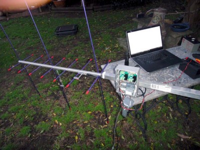
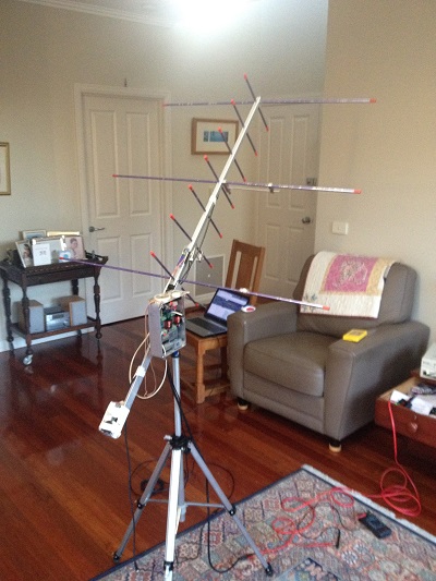
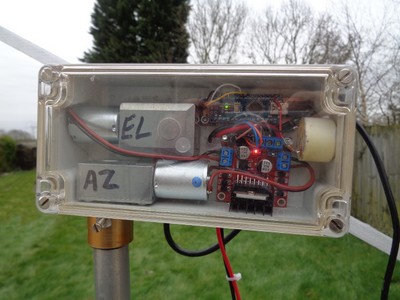
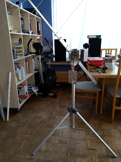
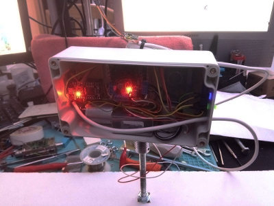
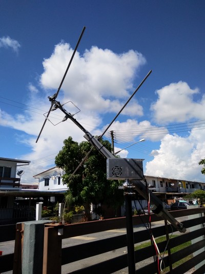
This project is a portable device used to automatically point a directional antenna towards an orbiting satellite. It takes all the effort out of little kids holding the antenna and figuring out where to point it. It allows students to listen to satellite beacons, talk through Amateur Radio satellites or download weather satellite images. Note: This is a complex DIY project for the advanced kit constructor.
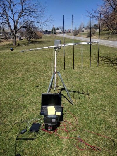
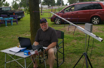
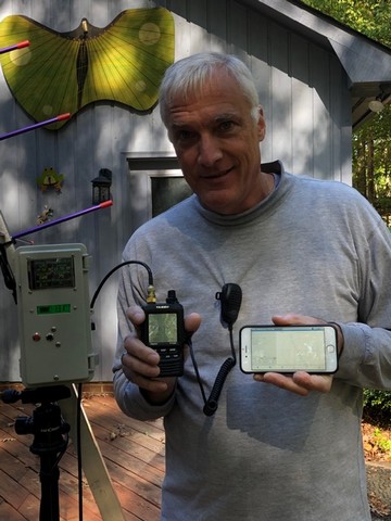
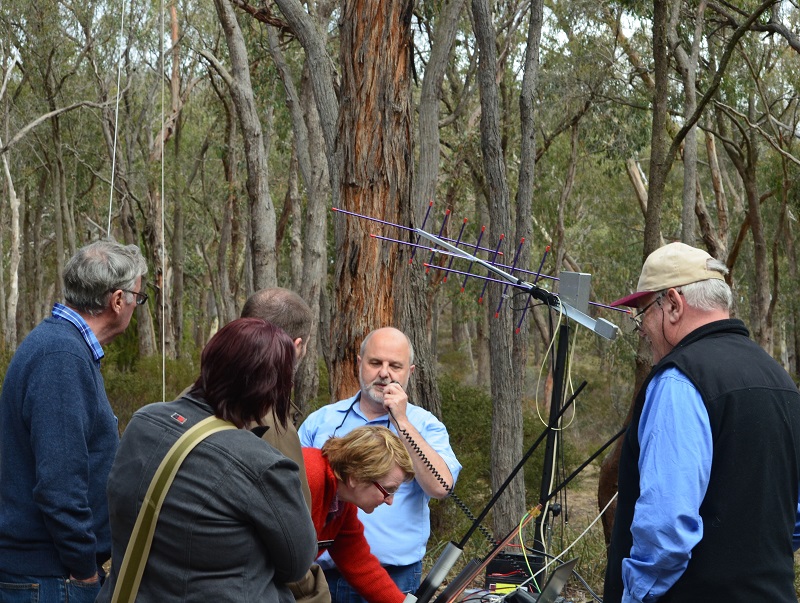
Here is the whole SARC crew out on the playground at lunchtime with Julie and Mr. Michael Day, their principal. They are using our solar-powered, portable, amateur radio satellite receiving station to communicate through AMSAT FO-29. Let's see what they've got going:
- 20W solar panel
- 10A MPPT Solar Charge Controller
- 12V 7AH SLA Battery
- 12V-USB Power Converter
- Raspberry Pi, running Gpredict and HAMLIB rotctld/rigctld
- LCD Monitor, Mouse and Keyboard
- Dual-band Arrow antenna
- Yaesu FT-817 transceiver
- Our Mini Satellite-Antenna Rotator Mk1


Table of Contents
- Description
- Parts List DC Motor Version
- Parts List AC Motor Version
- Project Status
- Latest Software
- Status reported by builders
- Problems experienced by some builders
- In the news
- Testing the Arduino Pro Micro stand-alone
- Assembly DC Motor Version
- Assembly AC Motor Version
- Installation
- Sensor Orientation
- Compilation/Upload Instructions
- Set to work instructions (Part 1)
- Calibration Instructions
- Set to work instructions (Part 2)
- SARCTRAC Earth
- Operating Instructions
- Cautions
- Safety
- Limitations
Description
Here is the draft of our original article which appeared in the May 2016 edition of Amateur Radio magazine. Warning: The Mini Satellite-Antenna Rotator is not suitable for unattended operation or permanent outdoor installation. Any malfunction can cause harm or serious damage.
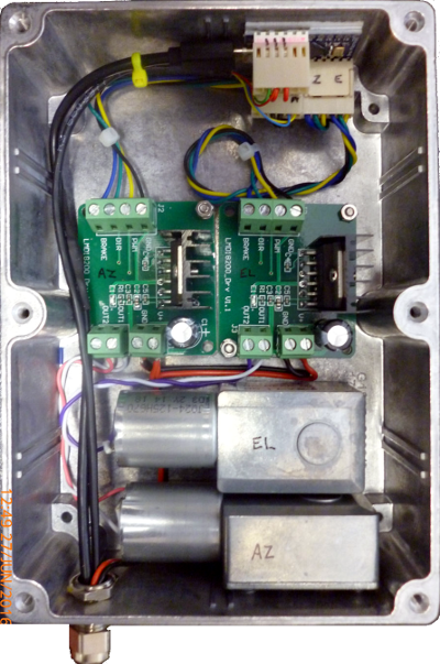
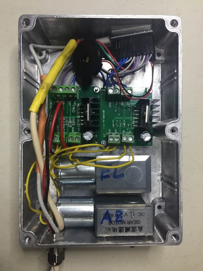
As of February 2025 this project has been completely updated to use the Arduino Nano controller. There are now only two versions of this rotator project: A DC motor version using an H-bridge driver and an AC motor version for Channel Master rotators using a triac driver.
The original versions of this project, used a Pro Micro controller. With its built-in USB programmer and a small profile this was a great solution at the time. However in March 2024, Windows 10/11 USB driver updates rendered this controller useless for operation with Gpredict and HAMLIB. The problem appeared to be that the USB port handshaking signals from HAMLIB were blocking the Pro Micro from sending its position feedback. This also caused Gpredict to crash. The only work-around for Windows with the Pro Micro was to use an external USB to TTL serial adaptor board connected to the Pro Micro TTL serial port.
Parts List (DC Motor Version)
All prices are shown in Australian dollars. Correct as at February 2025.

Parts List (AC Motor Version)
All prices shown in Australian dollars. Correct as at February 2025. This is the AC Motor version for the Channel Master TV antenna rotators. It uses an Aptinex, 4-channel, opto-isolated, Triac, Driver Board. There is a video of the working controller is here and a video of the working rotator here. Note that the Azimuth rotator has to be modified using this modification procedure to remove the 360-degree stop pins. Caution: This modification will void the warranty. Note: The last step in the procedure requires you to drill out the two stop pins without leaving any metal swarf in the gearbox.

Project Status (Updated: 18 February 2025)
- Total number of reported builders: 1925
Please update your status by e-mailing us. You can send us pictures and reports of your progress.
Latest Software
Please do NOT email the kind folk below. Please be patient: We typically reply in 24 hours, but it may take longer to reply.
Release 1: Original release.
Release 2: Added support for hamlib 3.0.1. Added debug mode.
Release 3: Improved calibration and operation.
- Added a low pass filter to the sensor data to improve calibration.
- Reinitialised the I2C bus and sensor prior to each read to avoid I2C lockups caused by power glitches
- Changed Serial to Serial1 for RS-422 operation
Release 4: Improved calibration and operation.
- Fixed a bug reading the EEPROM calibration data on some versions
- Made the SerialPort configurable to support both the Mk1 (USB) and Mk2 (RS422) rotators
- Added a speaker output to help with the calibration process
- Removed the overshoot inherent in the anti-windup algorithm
- Initialised the sensor filters at start up
- Added a pause command, as requested
- Added a help menu, as requested
- Clarified sensor axis definitions
Release 5: Changes to support the half-price Mk1b version.
- Added compiler option for either the original LMD18200T or the cheaper L298N DC Motor H-Bridge Driver Boards
- Added compiler option to set the driver board type and the pins used
- Note: Only PWM pins 5, 6, 9 or 10 can be used for PWM motor drive output
- Added compiler option for either the original LSM303D or the cheaper LSM303DLHC Accelerometer/Magnetometer
- Replaced the passive piezo speaker with an active beeper to help with the calibration process (since there were not enough PWM outputs)
- Better object-oriented architecture
Release 6: Changes to support the AC Motor
- Added compiler option to support the Aptinex 4-Channel, Opto-Isolated, Triac Driver (also available on eBay) and the ChannelMaster Rotators
- Added a non-blocking timer class
- Fixed a bug to support Version 1.8.8 of the Arduino IDE for Linux
Release 7: Changes to support the Arduino Nano. 18 February 2025.
P.S. To use it, simply unzip the Rotator7 folder to your Arduino IDE sketchbook folder. Note: The default configuration is for the DC Motor version with the LSM303DLHC 3D Sensor. Please don’t forget to configure the Rotator7.ino file for the correct motor type, sensor type and serial port. The default configuration is as follows:
//User configuration section://Please uncomment only one of each of the following MotorTypes, SensorTypes and SerialPort types://const int MotorType = PWMDIR; //Please uncomment this line for the LMD18200T DC motor driver.const int MotorType = FWDREV; //Please uncomment this line for the L298N DC motor driver.//const int MotorType = ACMOTR; //Please uncomment this line for the triac AC motor driver.//const int SensorType = LSM303D; //Please uncomment this line to use the LSM303D sensor.const int SensorType = LSM303DLHC; //Please uncomment this line to use the LSM303DLHC sensor.#define SerialPort Serial //Please uncomment this line to use the USB port.//#define SerialPort Serial1 //Please uncomment this line to use the TTL port.
Status Reported by Builders
The following is a list of some of the builders who have completed the rotator and sent us their comments or pictures:Brian VK2XTC - Brian was the first to complete assembly in May 2016: "Just letting you know the new motors arrived yesterday. These ones are now the correct 0.6RPM rather than 6RPM. They drive correctly, slow to the correct point etc. It all seems to work."
Adrian VK4KL - "Woohoo!! It's working."
Roger VK4YB - "Built it for Owen, VK4FADW and the kids at the Caboolture Historical Village." Good job Roger! Here is the result.
Frank VK2FRW - Well done Frank! "Had a problem with one motor gearbox." Frank reports it works OK with HRD. Here is a photo
Colin VK3VGB - "I have completed your Mini Satellite - Antenna Rotator project and it’s just the best !!"
Keith VK3VKS - "I purchased all the material for the Mk1 rotator and am now interested in the Mk2."
Warren VK6HM - "I have previously built your first rotator and enjoyed it immensely."
Mark VK3ZQ - "Just building a version of the Mk2 electronics to mod my original Mk1."
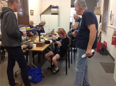
Robbie VK3XIN - "Great to see it working!" Robbie demonstrated his working rotator at Moorabbin and District Radio Club. It is shown here with the piezo speaker connected:
David G4FEV - "I have been quit brutal changing parameters and changing satellites while still tracking and everything is rock solid and performing perfectly. Frankly I am astounded. It is a thing of beauty to watch as it tracks whatever I tell it to or track manually using GPredict Rotator Control." Here is David's Mk1a version with the LSM303DLHC sensor and L298N motor driver board:
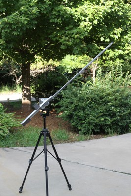
Hank AB2XG - "I can't say thank you enough for this project! I've wanted to try satellites for a couple of years now and have tried hand held antennas a couple of times, always seemed like there were just too many things to do all at the same time! Made my first contact today via SO50 using this. This setup takes aiming the antenna right off of your plate of things to do! Work the radio and adjust the polarization and your into the satellite." Here is Hank's setup with the Elk antenna:
Ed WA6WGS - "Many thanks for your patience. Your project is my first Arudino project... It is up and running, and wish to thank you again for the project." Here is Ed's setup with the Arrow antenna:
Dave EI4HT/M0GIW - "Hey all. Success today! It works! Thanks for your help! I'm on a Cypriot vessel between Ireland and UK. It works great here on the ship, fun to watch it compensate for heading and roll."
We are pretty sure Dave would have the first maritime mobile application of our Mini Satellite Antenna Rotator. In our original Amateur Radio Magazine article we said: “Even if the rotator mounting is moved during operation it will automatically reacquire the correct position, potentially making it suitable for land mobile or maritime applications.” But we never expected someone would actually try it! So well done Dave. Good job mate!

Dave EI4HT/M0GIW - More pictures of Dave's setup. He actually machined the hubs out of brass. Read his article about it in the Spring 2019 edition of AMSAT UK's Oscar News.
Alex ON5NV - We are very impressed at the way Alex has strengthened the mechanical parts with bearings.
Ronny ON5NR - A very professional build with what looks like a nice home-brew antenna. Ronny helped us update the Mk1a schematic to match the latest version of software. Thanks Ronny.
Eddie AE4TQ - "Just a quick email to follow-up and report that I have successfully finished constructing the Mini Satellite-Antenna Rotator project using the Mk1b design (L298N motor driver) this weekend. I have to say it is a real thing of beauty to watch it gracefully tracking satellites via Gpredict. Thank you again for sharing this project, I can't wait to show it off at one of our upcoming NFARL club meetings and to be able to use it for 2019 ARRL FD next summer!"
"I have made numerous contacts on the CAS-4A/B and XW-series satellites since I built this project, and it created a lot of excitement and interest when I demonstrated it at our recent N4N ARRL Field Day group gathering. Seems I've inspired a group project! I eventually settled on using a Raspberry Pi 3B to run gPredict 2.2.1 Ubuntu using standard USB connection, (since 2.2.1 supported the satellite auto-track feature, as well as the Easycomm II protocol for antenna feedback). It also nicely controlled my FT857D for tracking doppler-shift." I'm looking forward to using the set-up during Field Day in June to get some additional bonus points, and I have promised my local club, NFARL, an article for their eNewsletter, as well as offering to do a presentation at the September club meeting."
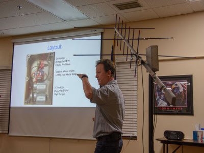
"I gave a presentation this month at my radio club, the North Fulton Amateur Radio League about the rotator project, which was very well received by the attendees, and thought I’d share a few pictures. I’ve received a lot of emails from club members both before and after the presentation. I can’t thank you again for sharing this project with everyone."
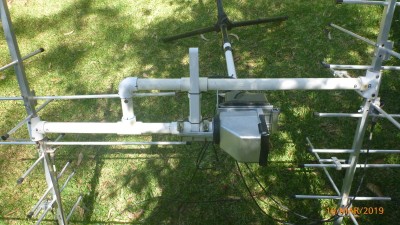
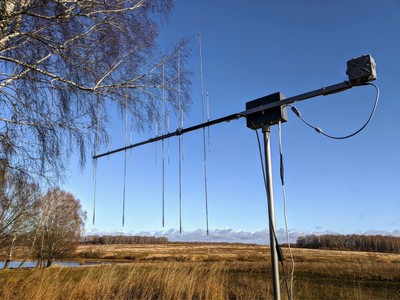
Bob VK2BYF - A very impressive looking antenna farm now with a Mk1 Mini Satellite Antenna Rotator.
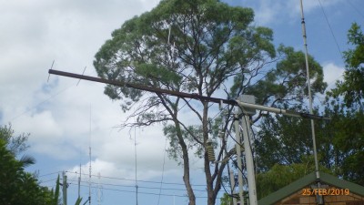
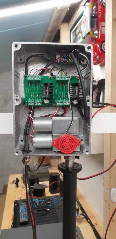
Bob VK2BYF - Also this heavy-duty AC motor version running on the same Arduino code. He says both are working perfectly. Well done Bob!
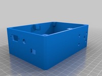
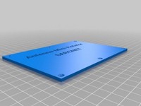
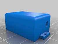
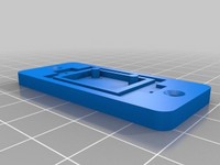
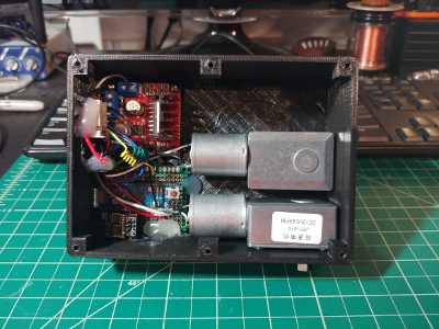
Béla HA4BM - Showing some real creativity and skill from Hungary, Béla has done an outstanding job designing his own 3D-Printed cases for the Mini Satellite-Antenna Rotator and the 3D Sensor.
He says "It is easy to reproduce using cheap 3D printers and PLA filament. The box is solid and meets the basic expectations. The dimensions are: 140mm x 100mm x 54mm."
Béla has kindly published his work, so that you can view his design and download his .stl files from here.
In testing his design, Béla noticed that using small steel screws to secure the 3D Sensor caused an offset in the position of the rotator. The solution is using non-magnetic, brass screws or just silicone adhesive for this purpose.
Kent K5WTS - Kent has an ingenious soulution for the lift-arm, with an integrated counterweight. By placing the sensor on the lift arm, away from the antenna, he also reduces RF interference from the I2C bus. Looks like a great portable setup Kent. Well done! Kent says: "Field day last weekend. It was a hit and a real attention getter. I have really enjoyed this project. Twelve years a ham and worked my first pile up on it. Five sat contacts in about three minutes. It's a hoot. Thanks for all you do with this Organization. 73s K5WTS Kent"
Denis VK6AKR from the West Australian VHF Group, based at the Wireless Hill Museum in Western Australia, reports that "Robert VK6FRDM is very well advanced with the construction of both the Mk1 and Mk2 Mini Satellite-Antenna Rotators. To the extent that he has demonstrated the Mk1 rotator to a group of school students and will possibly be establishing a continuing group at a local school. Robert's rotators were both on display at a HAMfest in Perth, where they attracted considerable interest from fellow operators." We know that Denis is also well on the way to completing his own Mk1 and Mk2 rotator. Well done and good luck to Denis and Robert!
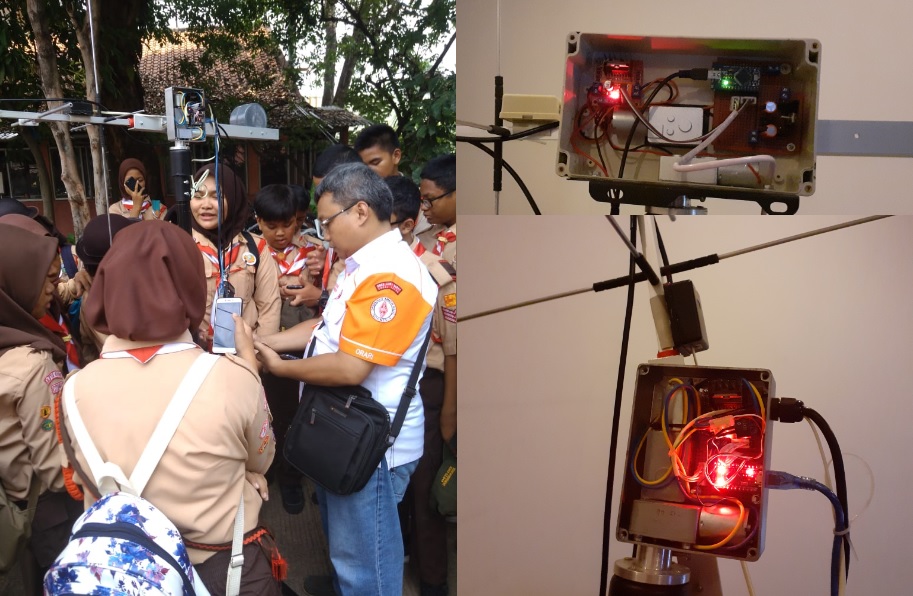
Bagus YD1DDK from Indonesia said "I have tried the Mini Satellite-Antenna Rotator Mk 1 - Arduino Light Duty and it has been successful and I have implemented it in JOTA 2019." We were really excited to see the Scouts at the demonstration. We are impressed at the way Bagus has experimented with the motor position and enclosures, too.
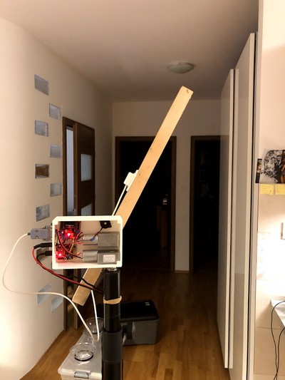
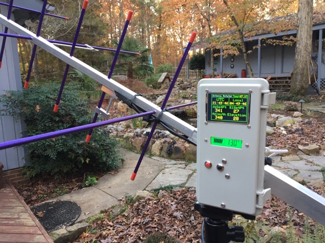
Mike K4TWM - "I added a few cool features to my set-up. I wanted a completely self-contained portable box that I could take camping to the beach or to the mountains. I included a 3.3Ah LiFePo4 battery and Raspberry Pi inside the box. I also wanted to see what was happening so I added a display so I can see the azimuth/elevation set points and sensor readings at a glance. I modified your program slightly to send az/el data serial data to the display. Starting with a full battery charge, I was able to run the system in demo mode (constant motion) continuously for 8 hours. Thanks again for the software, this has been a really fun project!"
Jon W2JON - "I am currently in the process of replicating your awesome project to work the birds with my 10-year-old son. My kid is chomping at the bit to get into some satellite and we are even building our own arrow style antenna. The work I have read on the site is phenomenal and I commend everyone involved and am especially touched by the efforts to help the children explore the wonders of ham radio and especially the satellite communications. We got the ESP8266 wireless serial bridge working well. Thank you for your consideration and thank you so much for sharing this project. 73, Jon W2JON." We note that Jon 3D printed the case by Béla HA4BM and also has the ESP8266 WiFi link working. Great work Jon!
Jon W2JON - "This is my scaled up version (semi-portable) of the MK1C. I built 2x 2 meter 4 element quads with nested 7 element 70cm yagi's built into the booms. Several custom 3d printed parts were made for the 2m element spreaders and feed point stabilizers. The 70 cm driven element has a custom 3d printed insert that centers the dipole and secures it as well. The rotators are old alliance U-100 style units which I totally tore down and rebuilt. This build uses the Aptinex 4 channel triac board and just like my portable build, it also has the wireless serial bridge in it via an ESP8266." - Jon's restoration of these old AC rotators was meticulous. The quads look amazing, too. Very impressive Jon!
Tony M0GLU - "Many thanks for the development. This is a great project. I didn't have any problems in the building process. It was easy and the documentation is great! 73s and best wishes! Tony."
Alton N4IDH - "All done! Works as published. I have now made a dozen Sat contacts with my IC-9700 and your fine rotator. One issue, the first sensor would never stabilize for azimuth. Luckily, I ordered 2. Second one works great. A surprise: Ham Radio Deluxe software controls the antenna great. Just select EasyComm II as the rotor. I have ordered a Arrow II antenna. First one was lost in the US Postal Service. Not a problem, Ham Radio Outlet is sending another via UPS and it arrives tomorrow. I am already collecting parts for the SARCTRAC. Two motors and an enclosure and I will be ready to start construction."
Kay DL9IM - "Many thanks for sending me the software. The project is completed and pictures are attached to this email. Thanks a lot for this great instruction, the first 2 qso's are already in the log."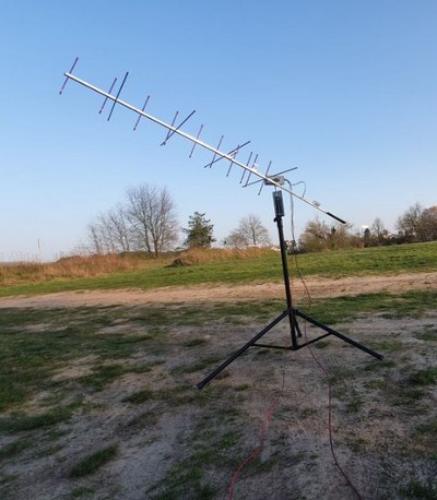
Szymon SQ5OVK - "I have completed the rotator."
Chris M0NAY - (MSAR Mk2) "I have only just got around to completing the rotator I started 18 months back due to work and other projects."

Stanley 9W8DNX - "I have completed my Mini Satellite-Antenna Rotator a few days ago. Attached here are the pictures of my completed project. I am very happy with the good results of tracking a few amateur satellites like PO 101, IO86, A027, AO 91, AO 92 and SO 50. This is my first time building my own tracker using Arduino and I am very grateful for the guidance and info from your website."
Andy AE8J - "Design is complete for my version of the mini AZ EL satellite rotator. Attached are a few 3D model views. I am a retired ham with a small machine shop in my garage. Most of the machined parts are complete."
Brian AB6AD - "I have just finished Mini Satellite Antenna Rotator project with AMSAT SA Dual Band Yagi. It is an excellent design and working. Thank you !"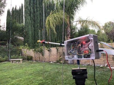
Viacheslav R2DZE - "Glad to report that I have successfully completed and field-tested the rotator as per your design! A couple of deviations are added esp8266 as COM-port bridge over WIFI and LED instead of buzzer. And as promise attaching some pictures as well. Thank you very much, it is pleasure to build it and operate!"
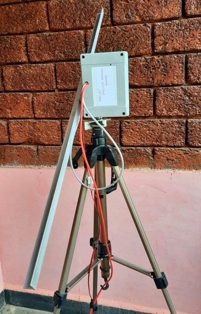
Ismael Garcia - "Hi! First of all I would like to thank you for the arduino code and congratulate you for the magnificent work. I think it is an exciting and fun project to build, I have not had any problems in the construction thanks to your wonderful instructions. Now I just need to build the antenna. I will try to build a 137 mghz yagi for the reception of meteorological satellites noaa. I currently use a quadrifilar. I send you some photos of the rotator. Thanks again and best regards from Spain."
Amey VU2YQ - "Thank you for your support during the debugging session. I have attached some of the pics of the antenna rotator in its early form with this email. I intend add an ESP8266 for WiFi interface. I shall send more pics in future once with further updates. This is a wonderful project and the code for Arduino is very professionally developed. Thank you for the project. I hope more folks from our local ham radio club shall build this rotator."
Las M0BOY - "Finally, a few months back I managed to finish the project. The main improvement I made is to put the compass on the back of the boom to avoid RFI and also note the Bluetooth serial module hm-10. All it needs is power lead and a raspberry pi to run rotctld and gpredict. Also, note that I am progressing a bigger version with toothed belts and cross polarised antennas. Hoping to finish it in spring." Las has a great video of it working here. Well done Las! Good luck with the Mk2 Version.
Problems Experienced by Readers
The following problems were reported by some of our readers. We have added our comments in bold.
- Original version of software assumed the EEPROM was initialised. Fixed.
- The m command does not work: The m command won't work properly, as indicated by "nan" (not a number) in the output, until the magnetic declination is entered and the calibration is completed. If the problem persists, try the b command to check that the 3D sensor is working properly.
- Ordering the wrong parts on eBay: 2 motors (reordered). Oops!
- eBay parts dead on arrival: 1 motor, 2 driver boards (reordered). That's a worry!
- Trouble finding a suitable satellite antenna: We use the Arrow II 146/437-10W from here: http://www.arrowantennas.com/arrowii/146-437.html.
- The 6mm hub is closer to 6.5mm. Yes, frequently 1/4" is sold as 6mm and vice-versa. Cut a soft-drink can for shim to pack the gap if necessary.
- The rotator azimuth and elevation motors just turn continuously. The sensor needs to be attached to the antenna boom and the rotator mounted on a sturdy tripod.
- Better serial monitor support: A help command. A stop and start command. Motor test command. Command error handling. All good ideas! We added Help and a Pause command.
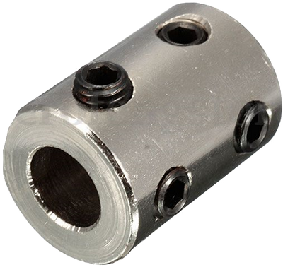
- The rotator wobbles too much. We have found that the original soft-brass shaft coupler used for the azimuth mounting wears out after repeated assembly/disassembly. It never seems tight enough: The rotator wobbles from side to side and at high elevation angles the lift arm hits the tripod upright. We have tested the following 4-screw steel shaft coupler from eBay and can report much better stability with it. However, using a second shaft hub for the azimuth mounting is by far the best and cheapest mounting method. For ease of tightening the shaft hub mount, the two small grub screws were replaced with 3mm cheese-head or cap screws. Some readers have re-tapped the holes to 4mm.
- Gpredict does not display the rotator position on a Windows PC, but the rotator works fine. Easycomm II rotator position feedback does not work on a Windows PC because of a handshaking issue when using the Pro Micro controller with HAMLIB. A work-around is to use a USB-TTL Converter connected to the TX, RX, GND and VCC pins on the Arduino and changing the code to use the Serial1 port instead of the Serial port. It works OK using the USB port with a Linux PC.
- RFI and EMC problems: The electronics generates RF Interference, which can be heard in the receiver while tracking satellites. Transmitting as little as 10W into the antenna can lock up, reset or even fry the electronics. We have done a lot of investigation in these areas and have a lot of feedback ranging from there is no problem at all through to unworkable situations. The fact is that every assembly and installation is different and we can't address every situation. So here are some tips for you to try: Place the sensor on the boom away from the driven elements - or better still on the lift arm. Try overall-shielded cable for the I2C bus. Add 0.1uF caps from the motor terminals to the motor chassis. Run a couple of turns of the antenna, I2C and USB/RS422 cables through ferrite toroids. Use low power, shielding and grounding techniques.
- The motors from China did not work: The motors brushes have a propensity of lifting off the commutator due to shock and vibration in transit. They can often be restored to operation simply by "tickling" the brushes with the power applied by inserting a squashed wooden toothpick through the crescent shaped holes. A spray of isopropyl alcohol through the holes may also be necessary to shift any grease on the commutator.
- The rotator points in the opposite direction and oscillates. The different motor suppliers are not consistent with the red-dot polarity marking on their motors. Some motors turn in the wrong direction. If you experience this problem, simply reverse the motor wiring.
In the News
- We submitted our original article to Amateur Radio magazine in December 2015 and again in February 2016. It was published in the May 2016 edition.
- We demonstrated the Mini Satellite-Antenna Rotator Mk1 to the Amateur Radio Victoria Homebrew Group.
- AR Magazine, June 2016. SOTA and Parks News by Allen Harvie VK3ARH. VK3 Show and Tell - Sunday 17 April 2016 - Brisbane Ranges National Park: "... Another highlight, among many, was provided by Joe VK3YSP. Joe set up his Portable Satellite gear, complete with mini computer controlled rotator for a demonstration earlier in the day and was ready and waiting for an early afternoon pass of amateur satellite designated FO-29. Right on cue, FO-29 came over the horizon and Joe completed what is believed to be the first WWFF contact from an Australian VKFF Park via Satellite. Joe exchanged greetings from the Park, the Park designator and name, and a valid signal report with Geoff VK2ZAZ. This was an effort by Joe and enjoyed by all present."
- We presented and demonstrated the Mini Satellite-Antenna Rotator Mk1 at GippsTech 2016 on July 9th & 10th 2016.
- We demonstrated the Mini Satellite-Antenna Rotator Mk2 to the Amateur Radio Victoria Homebrew Group
- We demonstrated the Mini Satellite-Antenna Rotator Mk2 to the Melbourne Space Program team on March 18 2017.
- We demonstrated the Mini Satellite-Antenna Rotator Mk2 at the Wireless Institute of Australia AGM on May 21 2017.
- We presented and demonstrated the Mini Satellite-Antenna Rotator Mk2 at GippsTech 2017 on July 1 2017.
- We demonstrated the Mini Satellite-Antenna Rotator Mk1 to the South East Radio Group on June 10 2018. It won first choice of the Home Brew prize!
- We presented and demonstrated the Mini Satellite-Antenna Rotator Mk3 and Mk4 at GippsTech 2018
Testing the Arduino Nano stand-alone
Use this test to check that the Arduino Nano and Arduino IDE are working correctly before wiring up the Arduino IDE.- Install the latest version of the Arduino IDE from https://www.arduino.cc/en/Main/Software.
- Connect the Arduino Nano via a mini USB cable to the PC USB port.
- Open the Arduino IDE.
- Select File | Examples | 01.Basics | Blink.
- Select Sketch | Verify/Compile (Ctrl+R). You should see "Compiling sketch..." followed by "Done compiling"
- Select Tools | Board | Arduino AVR Boards | Arduino Nano.
- Determine the virtual serial port used by the controller:
- On Linux start a terminal window and type: dmesg | grep "USB ACM device" Make a note of the tty devices.
- On Windows start device manager and look under "Ports" for "USB Serial Device" or "Arduino". Make a note of the "COM" numbers.
- Plug the Arduino Nano into the PC using the USB cable
- Repeat step 6 and identify the new tty device or COM port number
- Select Tools | Port and the tty device or COM port number that was added.
- Check the bottom line of the Arduino IDE shows "Arduino Nano on" and the correct COM port of tty device.
- Select Sketch | Upload (Ctrl+U). You should see "Uploading...". The Arduino Nano LEDs will flash. Then see "Done uploading".
- This indicates that you can successfully compile and upload an Arduino file.
- If you can't upload. May we suggest these steps before trying to upload again:
- Try selecting Tools | Processor | ATmega328P (Old Bootloader)
- Try closing the IDE. Disconnecting and re-connecting the controller. Starting the IDE again.
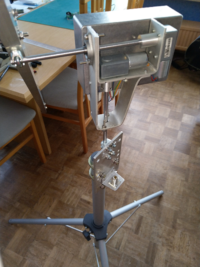
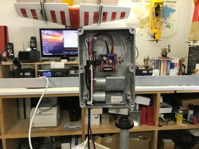
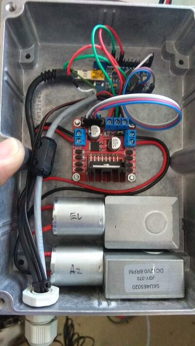
Assembly (DC Motor Version)
- The hardest part of the build was precision-marking and drilling the holes in the Enclosure. We recommend sticking adhesive paper labels to the outside of the Enclosure, scribing construction lines on them using a digital vernier caliper, centre-punching and drilling pilot holes first. A drawing of the Motor mounting holes can be found in the Motor datasheet here. Check three times - drill once.
- Drill 1 x 2mm Beeper mounting hole.
- Drill 8 x 3.5mm Motor mounting holes.
- Drill 4 x 3.5mm Motor Driver mounting holes.
- Drill 2 x 6.5mm Motor shaft holes.
- Drill 1 x 20mm Cable Gland hole with a step drill.
- Slightly countersink the Motor shaft holes on the inside of the Enclosure for the O-rings.
- Install 4 x M3 x 6mm tapped nylon Spacers for the Motor Driver to the inside of the Enclosure using 4 x M3 x 8mm pan head screws.
- Install a Cable Gland on the bottom of the Enclosure for the PC, Power and Sensor cables.
- Mount a Cable Tie Saddle to the 3rd boss from the left at the top of the Enclosure using a 4G x 6mm pan head self tapping screw.
- Pass a small Cable Tie through the Cable Tie Saddle, but do not fasten.
- Consult the schematic diagram below.
- Cut the +12V track on the rear of the Motor Driver board between the two solder pads.
- Solder a 1N5819 Schottky Diode between the two solder pads, with the white band (cathode) facing into the PCB.
- Solder 150mm of orange, purple, blue and grey hookup wire from the Arduino Nano pins D5, D6, D9 and D10 to the Motor Driver pins IN1, IN2, IN3, IN4.
- Solder 1m of yellow, green and black wires, from the 4-way telephone cable, to the Arduino Nano pins A4, A5, GND
- Solder 1m of red wire, from the 4-way telephone cable, and 150mm of red hookup wire to the Arduino Nano 5V pin.
- Solder 150mm of red and black hookup wire from the Arduino Nano pins D11 and D12 to the Beeper pins + and -. Use heat-shrink tubing over the Beeper pins.
- Solder 150mm of black hookup wire to Arduino Nano GND pin.
- Connect the free red and black hookup wires from the Arduino Nano to the Motor Driver 5V and GND terminals.
- Solder 150mm brown and black hookup wires to the Motor + and - pins. Cover solder joints with heat-shrink tubing.
- Connect Motor Driver OUT1 and OUT2 terminals to the Azimuth Motor black and brown wires.
- Connect Motor Driver OUT3 and OUT4 terminals to the Elevation Motor black and brown wires.
- Note: Be prepared to reverse the motor wiring as the motor direction of movement is not standardised.
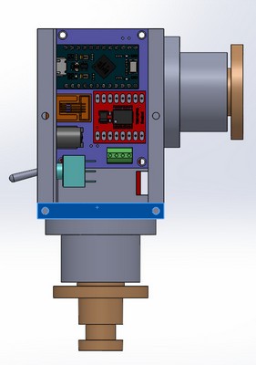
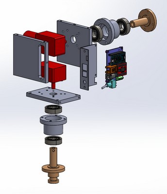
- Consult the assembly diagram below.
- Pass the USB Cable mini USB connector through the Cable Gland from outside the Enclosure.
- Connect the USB Cable mini USB connector to the Arduino Nano, passing the cable between the Motor Driver spacers.
- Secure the Arduino Nano to the Cable Tie Saddle using the Cable Tie.
- Crimp and shrink an Automotive Bullet and Socket connector in series with the ground wire of the Power Cable 150mm from one end as a Quick-Disconnect safety device. The Automotive Socket connector should be closer to the short end.
- Pass the Power Cable, Quick-Disconnect end, through the Cable Gland from the outside of the Enclosure.
- Connect Motor Driver V+ and GND terminals to the red and black power cable. Note: Check that the two black wires are properly secured in the same terminal.
- Pass the Sensor Cable from the Arduino Nano between the Motor Driver spacers and through the Cable Gland
- Slip 5mm O-rings over the Motor shafts before assembly. The O-rings are important for ingress protection, but their friction also counters some motor backlash in operation.
- Mount the Motors with 2 x M3 x 6mm pan head screws and 2 x M3 x 8mm pan head screws, each, with the longer screws associated with the following washer arrangement. Warning: If either set of screws is too long they will penetrate and damage the gearbox.
- Add two flat washers to the AZ motor mounting screws on the side near the lid to counter the chamfer in the rotator case.
- Add two flat washers to the EL motor mounting screws on the side near the top to counter the droop in the horizontal drive shaft.
- Install the Motor Driver on the nylon Spacers, over the USB and Sensor Cable, with 4 x M3 x 6mm countersunk screws.
- Apply a little super-glue to the front face of the Beeper. Insert a 2mm drill shank 5mm into the beeper hole in the Enclosure. Position the Beeper hole over the drill shank. Use the drill shank to guide the Beeper into final position. Hold the Beeper against the Enclosure for 60 seconds to permit the super-glue to set.
- Secure the Power, Sensor and USB cables in the Cable Gland.
- Solder the Sensor Cable to the 3D Sensor and enclose it in adhesive heat-shrink tubing to weather-proof it.
- Connect the USB Cable to the PC USB port.
- Connect the Power Cable to a 12 VDC, 1 Amp, Power Supply.
- Install A DC safety cutoff switch.
- WARNING: These DC Motors are so powerful that they will cause severe damage and harm due to any malfunction or error. Never to be used unattended.

Schematic Diagram


Assembly Diagram
Assembly (AC Motor Version)
- The AC Motor version uses external rotators, but the electronics are mounted in the same enclosure as the DC Motor version.
- Drill 1 x 2mm Beeper mounting hole.
- Drill 4 x 3.5mm Triac Driver mounting holes.
- Install 4 x M3 x 6mm tapped nylon Spacers for the Triacr Driver to the inside of the Enclosure using 4 x M3 x 8mm pan head screws.
- Install a Cable Gland on the bottom of the Enclosure for the PC, Power and Sensor cables.
- Mount a Cable Tie Saddle to the 3rd boss from the left at the top of the Enclosure using a 4G x 6mm pan head self tapping screw.
- Pass a small Cable Tie through the Cable Tie Saddle , but do not fasten.
- Consult the schematic diagram below.
- Solder 150mm of orange, purple, blue and grey hookup wire from the Arduino Nano pins D5, D6, D9 and D10 to the Triac Driver pins IN1, IN2, IN3, IN4.
- Solder 1m of yellow, green and black wires, from the 4-way telephone cable, to the Arduino Nano pins A4, A5, GND
- Solder 1m of red wire, from the 4-way telephone cable, and 150mm of red hookup wire to the Arduino Nano 5V pin.
- Solder 150mm of red and black hookup wire from the Arduino Nano pins D11 and D12 to the Beeper pins + and -. Use heat-shrink tubing over the Beeper pins.
- Consult the assembly diagram below.
- Pass the USB Cable mini USB connector through the Cable Gland from outside the Enclosure.
- Connect the USB Cable mini USB connector to the Arduino Nano, passing the cable between the Motor Driver spacers.
- Secure the Arduino Nano to the Cable Tie Saddle using the Cable Tie.
- Pass the Sensor Cable from the Arduino Nano through the Cable Gland
- Install the Triac Driver on the nylon Spacers, over the USB and Sensor Cable, with 4 x M3 x 6mm countersunk screws.
- Apply a little super-glue to the front face of the Beeper. Insert a 2mm drill shank 5mm into the beeper hole in the Enclosure. Position the Beeper hole over the drill shank. Use the drill shank to guide the Beeper into final position. Hold the Beeper against the Enclosure for 60 seconds to permit the super-glue to set.
- Secure the Sensor and USB cables in the Cable Gland.
- Solder the Sensor Cable to the 3D Sensor and enclose it in adhesive heat-shrink tubing to weather-proof it.
- Connect Triac Driver LOAD-1, LOAD-2 to the AZ Motor.
- Connect Triac Driver LOAD-3, LOAD-4 to the EL Motor.
- Note: Be prepared to reverse the motor wiring as the motor direction of movement is not standardised.
- Connect a 100uF 50V Bipolar Capacitor across each of the motor windings.
- Connect Triac Driver LOAD-1 Common and LOAD-2 Common to the 20VAC plugpack that comes with the AZ Channel Master rotator.
- Connect AZ Motor Common to the 20VAC plugpack that comes with the AZ Channel Master rotator.
- Connect Triac Driver LOAD-3 Common and LOAD-4 Common to the 20VAC plugpack that comes with the EL Channel Master rotator.
- Connect EL Motor Common to the 20VAC plugpack that comes with the EL Channel Master rotator.
- Install an AC Mains safety cutoff switch. Do not use AC Mains voltages outside.
- WARNING: These AC Rotators are so powerful that they will cause severe damage and harm due to any malfunction or error. Never to be used unattended.
- Connect the USB Cable to the PC USB port.
- Note that the Azimuth rotator has to be modified using this modification procedure to remove the 360-degree stop pins. Caution: This modification will void the warranty. Note: The last step in the procedure requires you to drill out the two stop pins without leaving any metal swarf in the gearbox - piece of cake :-).
- There is a video of the working controller here and a video of the working rotator here.

Schematic Diagram
Installation
- Note: The following parts required are not shown in the parts list, as individual requirements differ.
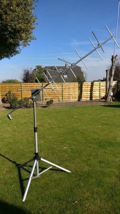
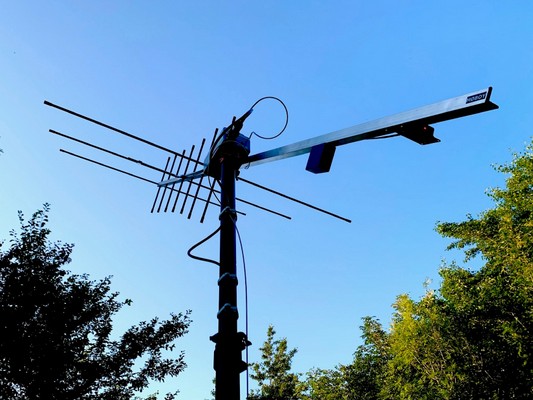
- Round the sharp edges of a Lift-Arm made from 500 x 30 x 30 x 3mm (or 1.6mm) aluminium angle.
- Make a Counterweight from a 101 x 51 x 25mm diecast aluminium box: Altronics H0451, Hammond 1590G or similar. Filled with lead to a total weight of 860g/1.9lb.
- Attach the Counterweight to one end of the Lift-Arm with a self-tapping metal screw.
- Attach the Arrow Antenna and cables to the Lift-Arm using Velcro. This is for quick release of the antenna and hand-held operation, if required.
- Find the balance point of the assembly by rolling the lift arm over a piece of dowel.
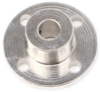
- Attach a 6mm Shaft-Hub to the Lift-Arm close to the balance point. Ours was 140mm from the antenna end. A slight front-heavy balance offset will reduce backlash. This might be provided by the antenna cables.
- Attach the Lift-Arm to the Rotator's EL motor shaft using the 6mm Shaft-Hub and tighten the hub screws, flat side first.
- Prepare an Extra Heavy Duty Speaker Tripod. Try Altronics C0520A. Remove the speaker bracket if fitted.
- Attach a 6mm Shaft-Hub to the top of the Tripod using a 25mm irrigation-pipe Threaded Plug, M3 x 12mm cheese-head screws, flat washers, spring washers and nuts. Fix with self-tapping screws to the tripod. Replace the grub screws on the Shaft-Hub with M3 x 4mm hex cap screws to obtain sufficient tighening torque.
- Attach the Rotator's AZ motor shaft to the tripod and tighten the Shaft-Hub screws, flat side first. Caution: Over-tightening the screws will strip the threads.
- Leaving enough slack for the rotator cables to wrap twice around the tripod mast Then secure the power cable to the mast using a hose clamp or split pin and cable tie. Should the rotator turn more than twice an any direction, the Quick-Disconnect device will activate to stop the rotator.
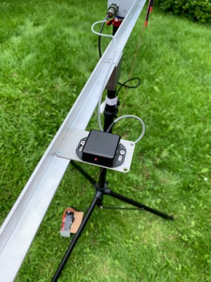
- Mount the flat side of the 3D Sensor against the top side of Lift Arm with double-sided tape or Velcro. See: Sensor Orientation for details. Keep the 3D Sensor away from the VHF/UHF driven elements to avoid RF interference to the sensor. Don't use high power for satellites. Use clip-on, ferrite cores on the 3D Sensor Cable if necessary.

Lift Arm Assembly

Tripod Mount
Sensor Orientation

The sensor is attached to the antenna boom and is aligned with the antenna reference axes (X, Y and Z shown in red above) as follows: With the antenna horizontal and pointing North, X points due East, Y points due North, along the antenna bore-sight, and Z points up. Please disregard any axes printed on the PCB.
Because the flat side of the sensor board is attached on the top of the antenna boom, with the long side of the sensor board parallel to the boom, the sensor axes (X', Y' and Z', as sometimes printed on the PCB) are not the same as the antenna reference axes (X, Y and Z) as used in our software and our original article. Instead, X = -Y', Y = X' and Z = Z'. Also, the gravity field vector G is the opposite of the device acceleration vector A.
Therefore the following transformations of the Magnetic (M) and Gravity (G) vectors are applied by our software:
MX = -MY', MY = MX', MZ = MZ', GX = AY', GY = -AX', GZ = -AZ'.
Compilation/Upload Instructions
- Open the Arduino IDE.
- Select File|Preference to find out your sketchbook location.
- Open the Mini Satellite-Antenna Rotator Arduino code file (Rotator7.zip).
- Copy the Rotator7 folder to your sketchbook location.
- Select File|Open|Rotator7|Rotator7.ino. You should see thirteen files open in the IDE as shown below.
- Select Sketch Verify/Complile (Ctrl+R). You should see "Done compiling" and no errors.
- Select Sketch Upload (Ctrl+U). You should see "Done uploading" and no errors.

Set to Work Instructions (Part 1)
- With the rotator assembly completed it is time to test the 3D Sensor and Controller
- Connect the Mini Satellite-Antenna Rotator controller USB port to a PC or Raspberry Pi or whatever, but do not connect the 12 VDC or 20 VAC motor supply.
- Start the Arduino IDE and open the rotator sketch
- Press Upload to reboot the Arduino
- Start up the IDE Serial Monitor (button at top right). Select "Carriage return" from the dropdown box.
- Type h<Enter> to display the help menu:
Commands:az el -(0..360 0..90)r -ReseteNN.N -MagDeclc -Calibrates -Savea -Abortd -Demob -Debugm -Monitorp -Pause
- Type b<Enter> to enter the debug mode and display the raw sensor data (Mx, My, Mz, Gx, Gy and Gz):
Debugging in progress: Press 'a' to abort18,-780,-219,2175,16178,582518,-780,-219,2178,16180,582718,-780,-219,2179,16181,582818,-781,-219,2179,16182,583018,-780,-219,2179,16184,583018,-781,-219,2180,16186,583218,-781,-219,2182,16189,583518,-781,-219,2182,16191,583418,-781,-219,2182,16193,583618,-781,-219,2181,16195,5835
- As you turn the sensor all around you should see each of the six numbers changing from positive to negative over approximately the same range.
- Type a<Enter> to abort the debug mode
Calibration Instructions
A workable calibration can be achieved entering the magnetic declination in your area, entering the calibration mode and turning the 3D Sensor around to point in 12 different directions. The Beeper stops beeping and the data stops changing when you have completed each point. The more care you take with the procedure the better the calibration will be. Once you have done the calibration properly it will not need to be repeated unless your magnetic declination or the magnetic conditions near the sensor change. A video of the calibration process is shown here.
- Go on-line to calculate the magnetic declination in your area. Go to http://www.ngdc.noaa.gov/geomag-web/. Enter your country and city. Press "Add Lat/Lon" then press "Calculate" to get your magnetic declination. Say it is 11 degrees, 40 minutes, East. Convert this number to decimal degrees by dividing the minutes part by 60 and adding it to the degrees part, so that's 40/60=0.7 plus 11 equals 11.7. Use a negative number (-11.7) if it says West instead of East.
- Make sure the 12 VDC or 20 VAC motor supply is disconnected. Connect the PC to the rotator using the USB cable.
- Start the Arduino IDE and open the rotator sketch.
- Press Upload to reboot the Arduino and start up the IDE Serial Monitor.
- Type in e11.7<Enter> to enter the magnetic declination (make sure you type in your own value). Then s<Enter> to save it.
- Now start the calibration process by typing c<Enter>.
- You can abort the process at any time by typing a<Enter>.
- When you have completed the calibration process, properly, just type s<Enter> to save the calibration data to non-volatile memory.
- To calibrate the sensor you have to move it around very, very slowly. Don't bump it in the slightest or even think about changing hands.
- It helps to tape the sensor and the sensor cable to the back of plastic or wooden ruler and hold the ends of the ruler in each hand.
- Move the sensor around. The Beeper will beep and you will see the 3D magnetometer (M) and accelerometer (G) errors and scaling factors changing on the screen.
- You can pretty much keep moving the sensor all around until the Beeper stops beeping or the data stops changing, but there is a trick to doing it properly.
- Think of the sensor as a cube with six faces. You need to point each face in the direction of the Earth's magnetic field and again in the direction of the earth's gravitational field. The gravitational field points straight down, while the magnetic field points up (in the Southern hemisphere) to the North at an angle of about 70 degrees to the horizontal. There are 12 directions and you have to move the sensor a little bit around each point until the Beeper stops beeping or the data stops changing.
- If you make a mistake type a<Enter> to abort the process.
- If all goes well type s<Enter> to save the calibration data when you have finished.
- You can then type r<Enter> to reset the controller and reload the stored calibration data. The calibration data is in the following format: MD, MEx, MEy, MEz, GEx, GEy, GEz, MSx, MSy, MSz, GSx GSy, GSz. Where MD is the Magnetic Declination, ME is the Magnetometer Error, GE is the Accelerometer Error, MS is the Magnetometer Scaling, GS is the Accelerometer Scaling.
Calibration in progress: Press 'a' to abort or 's' to save11.7,-11.0,10.0,1.0,-14.0,322.0,598.0,756.0,768.0,649.0,16277.0,16859.0,16303.011.7,21.0,-784.0,-218.0,2171.0,16295.0,5763.0,0.0,0.0,0.0,0.0,0.0,0.011.7,21.0,-784.0,-218.0,2170.0,16295.0,5762.0,0.0,0.0,0.0,1.0,0.0,1.011.7,21.0,-784.0,-218.0,2170.0,16295.0,5762.0,0.0,0.0,0.0,1.0,0.0,1.011.7,21.0,-784.0,-218.0,2170.0,16295.0,5762.0,0.0,0.0,0.0,1.0,1.0,1.011.7,21.0,-784.0,-218.0,2170.0,16293.0,5763.0,0.0,0.0,0.0,1.0,2.0,2.011.7,21.0,-784.0,-218.0,2169.0,16293.0,5763.0,0.0,0.0,0.0,2.0,3.0,2.011.7,21.0,-784.0,-218.0,2168.0,16293.0,5763.0,0.0,0.0,0.0,2.0,3.0,2.011.7,21.0,-784.0,-218.0,2168.0,16293.0,5763.0,0.0,0.0,0.0,2.0,3.0,2.011.7,21.0,-784.0,-218.0,2168.0,16293.0,5764.0,0.0,0.0,0.0,2.0,3.0,3.011.7,21.0,-784.0,-218.0,2168.0,16293.0,5764.0,0.0,0.0,0.0,3.0,3.0,3.011.7,-11.0,10.0,1.0,-14.0,322.0,598.0,756.0,768.0,649.0,16277.0,16859.0,16303.0Function aborted
Set to Work Instructions (Part 2)
- Once the calibration data is saved to the EEPROM you can continue to set the rotator to work.
- Make sure the 12 VDC or 20 VAC motor supply is disconnected. Connect the PC to the rotator using the USB cable.
- Start the Arduino IDE and open the rotator sketch.
- Press Upload to reboot the Arduino and start up the IDE Serial Monitor.
- In the IDE Serial Monitor type m<Enter> to enter the monitor mode.
- You should see the rotator data as shown below, comprising: Current AZ and EL, Setpoint AZ and EL, AZ windup angle, AZ windup state, AZ and EL error.
- Verify the Current AZ and EL numbers reflect the sensor true azimuth and elevation
- Make sure the lift arm is disconnected. Connect the 12 VDC or 20 VAC motor supply.
- Observe the IDE Serial Monitor display and observe the motor movement while looking directly at the motor shafts.
- Point the sensor North East. The first number should be between 0 and +90. The AZ motor should turn CCW.
- Point the sensor North West. The first number should be between 0 and -90. The AZ motor should turn CW.
- Point the sensor 45 degrees Down. The second number should be between 0 and -90. The EL motor should turn CW.
- Point the sensor 45 degrees Up. The first number should be between 0 and 90. The EL motor should turn CCW.
- If a motor moves in the wrong direction, reverse the motor wires by swapping the OUT1 and OUT2 connections on the appropriate Motor Driver board.
- Disconnect the 12 VDC or 20 VAC motor supply. Attach the rotator to a sturdy tripod or rigid mount. Attach the lift arm to the rotator. Attach the sensor along the bore-sight of the lift arm.
- Disconnect the USB cable.
- While carefully monitoring the lift arm, ready to disconnect the 12 VDC or 20 VAC motor supply if something goes wrong. Connect the 12 VDC or 20 VAC motor supply - there should be no movement.
- Connect the USB cable. The lift arm should swing around to 0 degrees AZ/EL and stop.
- Turn and tilt the tripod. The rotator should restore the lift arm to this home position.
- In the Arduino IDE Serial Monitor type m<Enter> then type 30 45<Enter>.
- The lift arm should swing around to approximately 30 degrees AZ and 45 degrees EL.
Monitoring in progress: Press 'a' to abort26,40,30,45,31,0,-4,-527,41,30,45,31,0,-3,-428,42,30,45,31,0,-2,-329,43,30,45,31,0,-1,-230,44,30,45,31,0,0,-130,45,30,45,31,0,0,030,45,30,45,30,0,0,011.7,-11.0,10.0,1.0,-14.0,322.0,598.0,756.0,768.0,649.0,16277.0,16859.0,16303.0Function aborted
SARCTRAC Earth - New for 2026
Instead of providing detailed instructions and endless debugging advice for other 3rd-party software (Gpredict™, HAMLIB™, SatPC32™, Orbitron™, PstRotator™ and HamRadioDelux™), we decided to build our own satellite tracker, called SARCTRAC Earth. Its free, has fast (10 Hz update rate) native drivers for our MSAR and SARCTRAC rotators as well as for ICOM and Kenwood transceivers, more drivers to follow. You can now easily decode CW beacons without the 1 Hz frequency jump. It supports HAMLIB rotators and transceivers as well, but at a 1 Hz update rate. It has a 6-hour satellite pass-predictor and a built-in satellite-frequency and mode database - just click on the displayed uplink, downlink or beacon frequencies and they become operational.

SARCTRAC Earth
SARCTRAC Earth for Earth orbiting satellites is a companion to our deep space tracker SARCTRAC Space
Operating Instructions
Note: The rotator can be controlled automatically via a satellite tracking application or manually by the user via a serial terminal emulator, such as PuTTY. Automatic tracker commands must be terminated with a Line-Feed character. User commands must be terminated with a Carriage-Return character.
Serial commands:
Enter two integers AZ and EL in degrees separated by a space to manually control the rotator. e.g. 270 45<Enter> Note: AZ here works in either 0~180~360 or -180~0~180 degree format.
- r - Reset. Prints the calibration data. Resets the rotator to the home position and resets the windup value.
- b - Debug mode. Prints the raw sensor data: Mx, My, Mz, Gx, Gy and Gz.
- c - Calibrate mode. Displays the calibration data only when it changes.
- d - Demo mode. Tracks linearly through the following AZ/EL points in a cycle: 0/0, 90/90, 0/180, 90/90 0/0, -90/90, -180/0, -90/90, 0/0
- m - Monitor mode. Prints current AZ and EL, set points for AZ and EL, the AZ windup angle, the AZ windup state, the AZ and EL error.
- a - Abort Calibrate, Monitor or Demo mode
- e - Enter Magnetic Declination. e.g. e11.7<Enter>. It is positive for East or negative for West.
- s - Save Magnetic Declination and Calibration Data.
- h - Help
- p - Pause
Cautions
Please read the following very carefully. We accept no responsibility or liability for the following:
- This is a DIY project for the experience builder. We are not responsible for your time, costs, tools, availability or substitution of parts.
- Beware of moving parts - Unit may move at any time without warning. Do not stand or permit anyone to stand in the vicinity of the operating unit.
- Beware of eye hazard - Moving satellite antennas are prickly. Eye protection is recommended.
- Beware of pinch hazard - Keep fingers away from moving parts.
- Beware of electromagnetic radiation hazard - Do not use with high power transmitters. Recommend 10 Watts maximum.
- Beware of electrocution hazard - Do not use near power lines.
- Beware of lightning hazard - Do not use in thunderstorms, rainy or windy conditions.
- Beware of fire hazard - The unit has no built-in over-voltage or over-current protection.
- Not suitable for unattended operation.
- Not suitable for fixed or permanent outdoor operation.
- Automatically connects to the Internet: Adult permission and charges may apply.
- Constant adult supervision of the operation is required to prevent injury, especially around children.
- Constant adult supervision of the operation is required to prevent damage to the unit, anything attached to the unit or anything in the vicinity of the unit.
- Constant adult supervision of the operation of radio transmitters is required at all times. You must check your licence conditions and operating frequency.
- Antenna, tripod, lift arm, mountings, cables or anything in the vicinity of the unit may be damaged under normal operation or due to software malfunction.
- The motors are light-duty and the antenna provides a lot of leverage on the motor shafts: Do not force them, tip over the tripod or drop its vertical shaft. Avoid striping the metal gears.
- Installation of a quick-disconnect connector in the power lead and safety DC cut-off switch is recommended.
Safety
We have conducted the following safety testing of the completed project:
- Motor stall: The motors do overheat or draw excessive current under full-power stalled conditions.
- Cable windup: The motors are very high torque. Cables can be damaged under windup conditions. The addition of a quick-disconnect power cable connector is recommended.
- Antenna impact: The Arrow™ Antenna elements were not damaged under full-power impact or restraint conditions.
- Human impact: The human is not damaged under full-power impact or restraint conditions. Note: Eye damage could occur even when the antenna is motionless.
Limitations
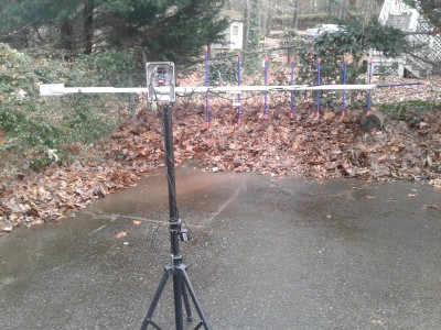
- Suitable for rotating only a single, small directional antenna (e.g. A handheld, dual-band, Yagi antenna such as an Arrow antenna) using a counterbalanced lift arm.
- Not suitable for applications requiring high pointing accuracy e.g. parabolic dishes for EME. +/- 5 degree accuracy is possible with optimal calibration, but is not guaranteed.
- Unit will oscillate unless solidly mounted only on a rigid stand, such as a heavy-duty (speaker) tripod.